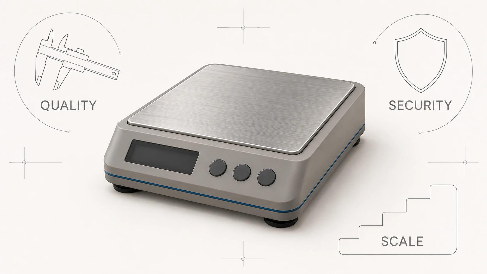
CAD, digital content creation (DCC) and real-time models solve different product-design jobs. Each is fit for purpose only when its representation, retained information and acceptance evidence match the next decision. These are working assets, not three quality settings for one universal file.
An engineering CAD model may preserve precise surfaces, assemblies and editable relationships. A DCC model may trade that construction logic for controllable topology, UVs, materials, cameras and animation. A real-time asset distils the product into geometry, textures, hierarchy and motion that a particular viewer can load and render. One can be derived from another, but a clean import or convincing preview does not approve the derivative for a new use.
This page owns that technical comparison. For the broader choice of inputs, accuracy levels and deliverables, use 3D Product Modeling: Inputs, Accuracy Levels and Deliverables. The stage-by-stage design handoff belongs in Product Design 3D Modeling: From Concept to Commerce Asset, not here.
Compare models by retained information and acceptance
The table below is an original Double Edged fit-for-purpose model comparison. It describes common working states, not a rule that every tool or extension behaves identically. A CAD application can work with meshes; a DCC can import precise surfaces; an engine can render more than glTF. The useful distinction is what the handed-off asset retains and what someone has actually checked.
| Working asset | Main representation and retained information | Work it is good at | Evidence needed at handoff | What must not be inferred |
|---|---|---|---|---|
| Native CAD authoring model | Precise solid or surface geometry, assembly structure, parameters, constraints, features and product metadata as supported by that system | Changing dimensions, preserving design relationships, configuring parts and supporting controlled engineering work | Native application and version, units, revision, assembly status, unresolved features, controlling requirements and named engineering authority | That the design is released, verified, manufacturable or visually ready merely because it opens in CAD |
| CAD exchange or direct-geometry model | Translated solids, surfaces, facets, assembly and metadata to the extent the source, translator and receiving system support them | Supplier exchange, downstream reference, inspection and rebuilding when native authoring data is unavailable | Source revision, export settings, import report, topology checks, dimensional checks and a list of information not transferred | Native feature history, editable design intent, complete PMI or lossless round-trip behavior |
| DCC visualization master | Polygon or subdivision geometry, object hierarchy, UVs, render materials, textures, cameras, lights, rigs and animation controls | Offline stills, closeups, product motion, material development and visual variants | Product comparison views, view envelope, material references, scene dependencies, renderer/version record and approved exceptions | Engineering authority, exact CAD editability, destination-neutral materials or automatic runtime performance |
| Real-time delivery asset | Tessellated mesh primitives, compact materials and textures, scene nodes, pivots and supported animation data | Web viewers, product customizers, interactive scenes and other named runtime destinations | Exact exported file, validator result, destination preview, device test set, feature fallback record and measured performance against the project budget | Authoring history, universal viewer support, offline-render parity or acceptable performance on an untested destination |
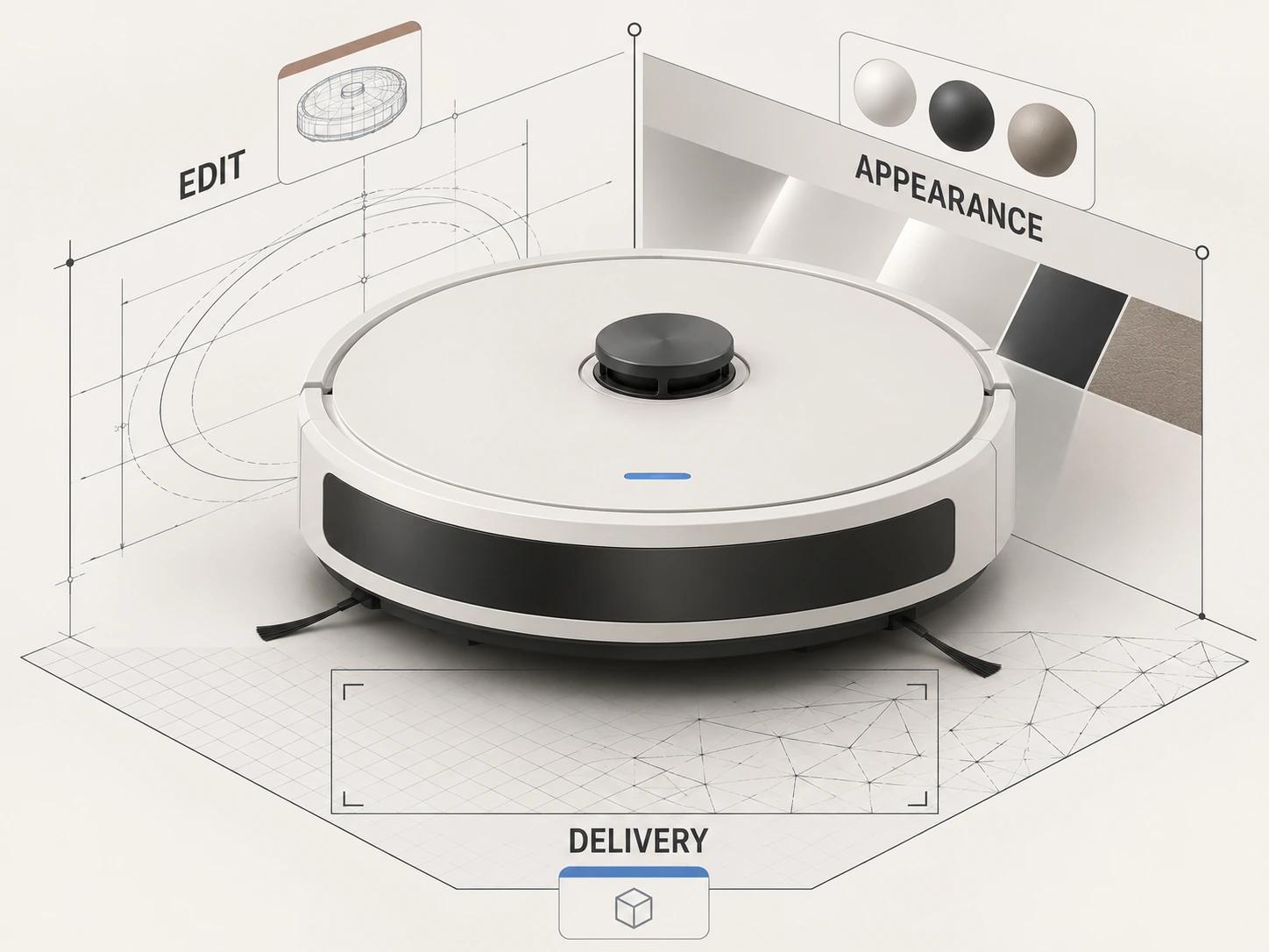
A buyer can therefore ask a better question than "Do we get the 3D model?" Ask which working asset is editable, which one controls approved appearance, which derivatives are included, and what evidence accompanies each.
CAD is more than a smooth shape
Precise and faceted geometry solve different problems. NIST describes facet data as triangular meshes that approximate surfaces, while precise boundary-representation geometry mathematically defines closed volumes for high-precision uses such as engineering analysis, manufacturing and inspection. Its discussion also covers hybrid models that combine both representations.[1] The presence of triangles is not automatically wrong, and a b-rep is not automatically released product data. The representation still needs context and authority.
Parametric intent is another layer. Autodesk's Fusion documentation offers a concrete example: its parametric mode captures features and relationships in a timeline, while direct modeling does not. When direct geometry becomes a base feature, later edits inside that feature are not reconstructed as individual parametric steps.[2] Other CAD systems differ, but the lesson travels well. A recipient can receive the visible shape without receiving the logic that made a hole follow a bracket, a pattern update with a count, or an assembly respond to a named parameter.
For an editable engineering handoff, specify the native authoring environment, feature and assembly expectations, required metadata, revision authority and permitted translation. For a reference handoff, say that direct geometry is acceptable and name the checks it must pass. Do not make the extension carry that contract by itself.
DCC models are built to make images and motion
A DCC visualization master is arranged for visual control. Its topology should hold the required silhouettes and reflections. Part splits, object names, pivots and hierarchy should support shot building and motion. UVs, textures and shader networks should reproduce approved finishes in the chosen renderer. Cameras, lights and render settings complete the scene.
Geometry alone cannot carry that appearance. Blender's current manual, for example, allows a mesh to have multiple UV maps and identifies the active render UV map as an input used by texture and UV nodes for material shading.[5] That is one implementation, not a universal recipe, but it shows why an imported mesh that looks complete in solid view may still be missing the data needed for a final image.
The visualization master may also contain render-time subdivision, procedural materials, displacement, linked texture files or renderer-specific nodes. Those choices can be entirely appropriate for offline production. They should be listed as dependencies rather than hidden behind a filename. The detailed craft of geometry, UV and material quality belongs in Photorealistic 3D Product Modeling: Geometry, UVs and Materials.
Tessellation is a controlled approximation
Tessellation samples precise curves and surfaces into polygons. It creates the mesh that DCC and real-time tools can draw, but it also introduces a measurable difference from the source. A coarse setting can flatten a circular housing or reveal facets in a highlight. An indiscriminately fine setting can create triangles that add transfer, editing and runtime cost without changing the approved view.
Autodesk VRED describes its tessellation tolerance as the maximum triangle aberration from imported b-splines and can create level-of-detail states from multiple tolerance values.[6] That is a product-specific control, not a cross-software preset. Chordal deviation, angular control, edge length and stitching can be named or implemented differently elsewhere.
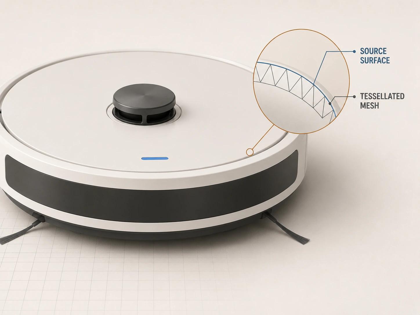
Record the source revision, units, orientation, tessellation method and settings, then inspect the derivative against its view envelope. Check silhouette, circular openings, panel gaps, thin parts, normals and seams at the closest approved camera. Keep the precise source so a later destination can be tessellated again rather than simplified from an already simplified mesh. The full conversion sequence, including cleanup, retopology, UVs and optimization, belongs in CAD to Web 3D: What Gets Converted, Rebuilt and Optimized.
Materials and animation expose hidden incompatibilities
Offline and real-time renderers do not necessarily interpret a material graph the same way. A layered automotive paint, procedural brushed metal or renderer-specific coating may have to be represented with a smaller supported parameter set and baked textures. The visual target should be an approved comparison under named lighting, not a promise of identical pixels in every renderer.
Motion needs its own contract. Blender describes DCC animation as object transforms, deformation and inherited movement, usually driven by keyframes; rigs can also involve armatures, constraints, shape keys and drivers.[7] A production rig built for an animator may contain controls that are never intended for export. For a product, list the moving parts, pivots, parent-child relationships, permitted ranges, resting state, clips and interaction logic. Then identify which of those must survive in each derivative.
Separate three things during review: the product's approved material and movement, the DCC implementation used to create images, and the subset encoded for the destination. Passing one does not settle the other two.
A real-time file is a publishing asset
Khronos defines glTF as an API-neutral runtime asset-delivery format and explicitly says it is not an authoring format. It can represent nodes, meshes, materials, textures, skins and animations, but deliberately omits general authoring information. The specification also leaves playback behavior such as starting, looping and ordering animations to the runtime.[3]
That boundary is useful. A delivery asset should contain what the viewer needs, not every construction feature, high-resolution texture source or animation control used upstream. Khronos's current real-time asset guidelines distinguish native authoring, interchange and delivery formats; describe triangle-based glTF geometry; and discuss baking DCC materials, reducing geometry, reusing meshes and optimizing textures for publishing targets.[4]
None of that creates one safe polygon count or texture size for every project. A single-product viewer, a configurator with many swappable parts and a scene containing several products spend different runtime budgets. Set acceptance against the actual destination: transfer size, decode and load behavior, memory, draw work, interaction, visual error and frame behavior on a named device set. A valid GLB that previews on one desktop has passed a useful check, not the whole release.
Product truth sits above file type
In this article, product truth means the controlled evidence for the product attributes the asset claims to represent. This is an original Double Edged operational definition, not a standard file type. The evidence may include a released CAD revision, drawings, part and variant records, finish references, current artwork, an approved sample, deviations and unresolved issues.
Build the baseline by attribute. Engineering may control a mating interface. Product operations may control the sellable variant list. Brand may control artwork. An approved sample may settle a visible texture that CAD does not describe. If two sources conflict, record the conflict and its owner rather than letting an artist choose the most plausible version.
Every CAD, DCC and real-time asset should name the product-truth baseline it represents and the attributes it intentionally omits. That makes a derivative traceable without pretending its file contains every fact about the physical product.
Use three acceptance lanes, not one approved flag
The following three-lane record is another original Double Edged framework. An asset can pass one lane and fail another. The same person may hold several roles, but each decision should remain explicit.
| Acceptance lane | Decision | Evidence to review | Pass statement |
|---|---|---|---|
| Engineering intent | Is the model editable and authoritative for the named design work? | Native or exchange state, parameters or direct-geometry limits, assembly and metadata checks, revision and engineering review | This exact asset may support the stated engineering use; no broader release or verification is implied |
| Offline visual production | Does the DCC master represent the approved product across the agreed images and motion? | Comparison views, dimensions that matter on camera, material references, UV and texture checks, hierarchy, rigs, dependencies and render tests | This scene may produce the named visual outputs within the approved view and variant envelope |
| Real-time destination | Does the exact derivative work acceptably in the named runtime? | File validation, scale and origin, hierarchy, materials, texture behavior, animation clips, fallbacks, destination ingestion and device measurements | This file revision may ship to the named destination under the tested conditions |
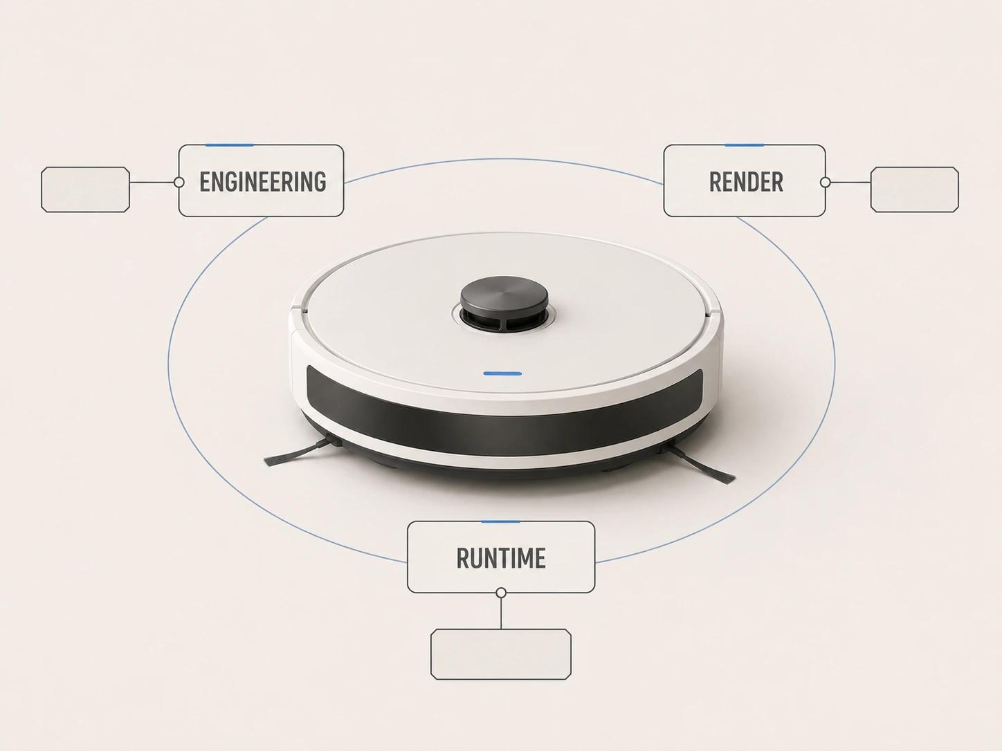
A single "approved" tag cannot express those decisions. Tie each pass to an immutable file or package revision. If geometry, material, texture, animation or export settings change, reopen only the affected lanes, but do not let the new file inherit approval silently.
Record what each representation retains and loses
A useful cross-representation handoff states:
- product ID, variant scope, product-truth baseline and effective date;
- each delivered asset's role: CAD authoring, CAD exchange, DCC master or named real-time derivative;
- native application, version, units, axes, origin, scale and external dependencies;
- retained parameters, features, assembly data and metadata, plus known losses;
- tessellation source and settings, rebuilt surfaces, retopology, omissions and presentation adjustments;
- material zones, UV sets, texture sources, renderer dependencies and real-time substitutions;
- hierarchy, pivots, moving parts, rigs, clips, limits and runtime interaction owned elsewhere;
- approved views and variants, destination, test devices, acceptance results and open issues;
- owner for engineering intent, visual representation and destination release;
- change rule linking every derivative back to its source revision.
Complex products make these boundaries easier to see. A vehicle can have trim geometry, interiors, wheel packages, moving parts and reflective finishes that branch into many channel assets. Automotive 3D Modeling for Marketing, Configurators and AR covers that product-specific case. The rule remains the same for a kettle, vacuum or machine: shared product identity does not require one unchanged file.
Choose the representation by its next decision
Ask what the recipient needs to change, show or run. If they must alter dimensions and preserve design relationships, scope a controlled CAD handoff. If they must produce closeups, motion and finish variants, scope a DCC visualization master with its dependencies. If they must publish an interactive product, scope a destination derivative and test it there. When several uses matter, deliver a traceable asset family rather than calling one export the master of everything.
The 3D product modeling service is the relevant commercial destination when source data must become controlled visualization and delivery assets for named uses. Bring one representative product, the available CAD or reference evidence, required variants, closest views, motion needs and target destinations so the handoff can be defined around acceptance rather than extensions.