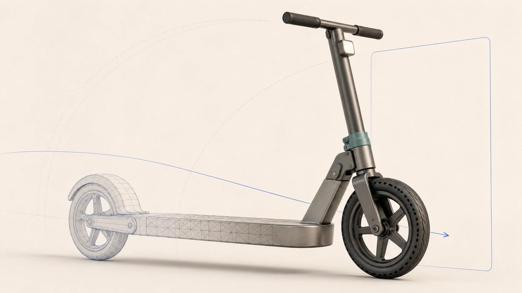
CAD to web 3D is rarely a clean file-format swap. The source may describe exact surfaces, assemblies and engineering structure. The browser needs renderable triangles, portable materials, textures and a scene hierarchy that can load and respond on the intended devices. Some information translates. Some geometry needs repair or reconstruction. Everything that remains has to earn its runtime cost.
A sound 3D CAD conversion services workflow therefore produces a traceable derivative, not a smaller substitute for the engineering master. Preserve the source revision, decide what the web asset must show and do, tessellate against that view envelope, rebuild only where the converted mesh fails, then test the exact GLB in each named destination.
Use this guide for the conversion and inspection work between controlled CAD and a tested web derivative. For source packages, accuracy classes and deliverable definitions, start with 3D Product Modeling: Inputs, Accuracy Levels and Deliverables. For the upstream relationship among concept, engineering definition and commerce assets, use Product Design 3D Modeling: From Concept to Commerce Asset.
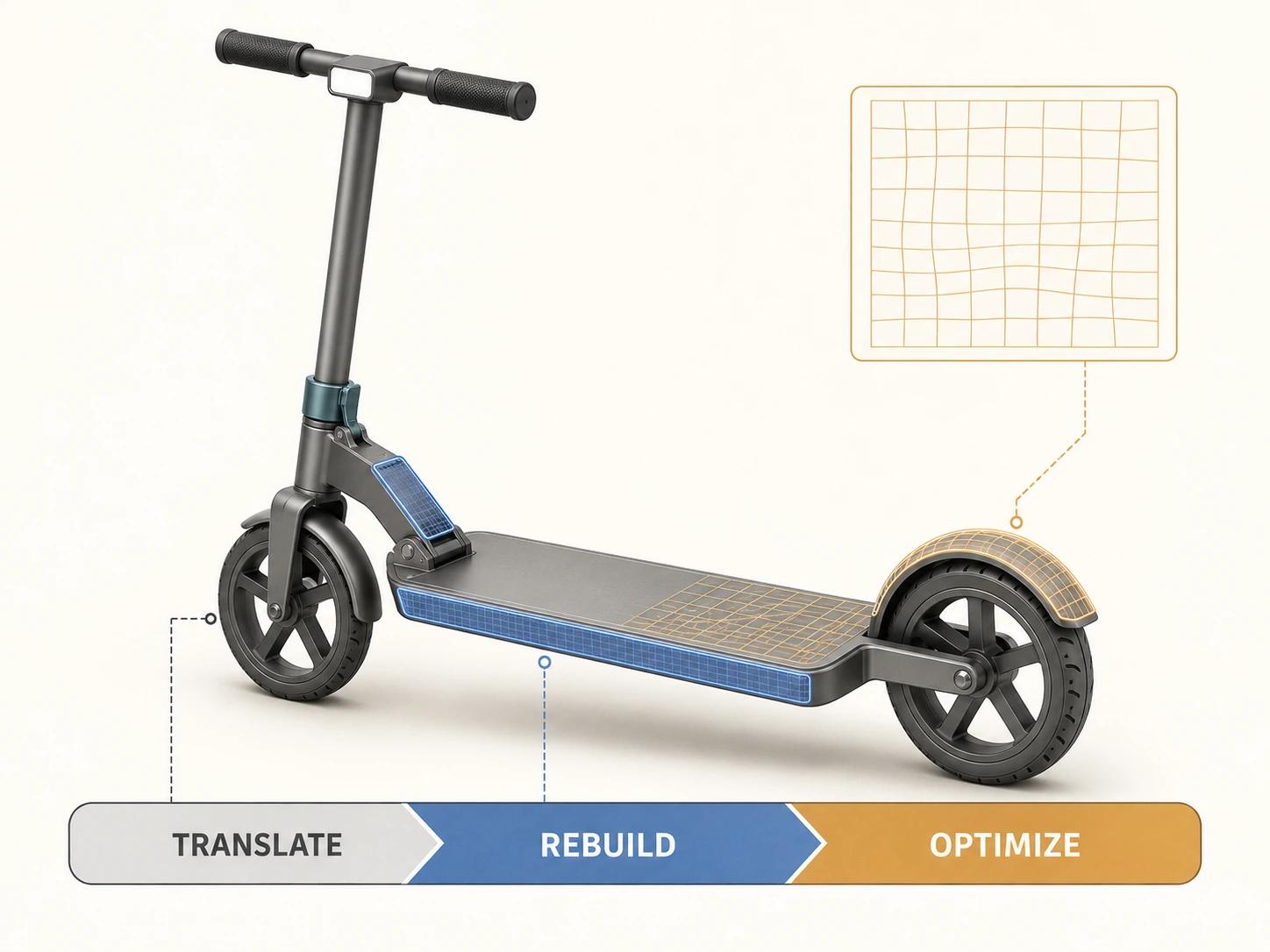
Conversion has three different kinds of work
A useful estimate separates the job before anyone quotes it as "CAD conversion":
- Translate information the target can carry: selected part geometry, hierarchy, names, transforms, cameras where useful, and material assignments that have an explicit mapping.
- Rebuild what translation cannot make production-ready: damaged surfaces, chaotic topology, animation-ready joints, intentional UV layouts, baked detail and materials designed for real-time rendering.
- Optimize and package the approved representation: remove unused data, simplify by perceptual importance, size textures for the viewing conditions, configure any supported compression or LOD strategy, export a self-contained GLB and inspect the final bytes.
The balance changes by product. A simple enclosure may tessellate cleanly and need little retopology. A large assembly can contain thousands of hidden fasteners, internal parts and repeated components that are valid in CAD but wasteful in a product-page viewer. A folding mechanism may need preserved part boundaries and deliberate pivots even if a static viewer could merge it into one mesh.
This three-part split is an original Double Edged estimating framework, not a standard. It prevents a translator's successful completion message from being mistaken for visual, product or destination acceptance.
Start with an auditable source, not whichever file opens
Precise CAD and polygonal meshes describe shape differently. NIST describes facet data as triangular meshes that approximate surfaces, while precise boundary-representation geometry is mathematically defined and used where high precision is required. It also notes that hybrid engineering models can combine precise and facet geometry.[1] A triangulated derivative can represent the approved visible form without retaining the source model's editable features, constraints or engineering authority.
Before conversion, record:
- source filename, native system or exchange format, revision and supplied date;
- units, coordinate orientation and intended product configuration;
- assembly references and whether all linked files are present;
- visible variants, moving parts and configuration rules that must survive;
- controlling dimensions and approved finish, artwork and transparency references;
- permitted omissions, simplifications and reconstructed areas;
- intended maximum view, interaction, animation and destinations.
Open the assembly with missing-reference reporting enabled. Compare part count and bounding dimensions with the sender's record. Suppressed, construction, envelope and hidden components need explicit treatment; visibility in one saved CAD view is not a reliable commercial inclusion rule. If the source package is incomplete or the as-sold product differs from the CAD revision, log the gap before mesh work begins.
Tessellation turns surfaces into a view-dependent approximation
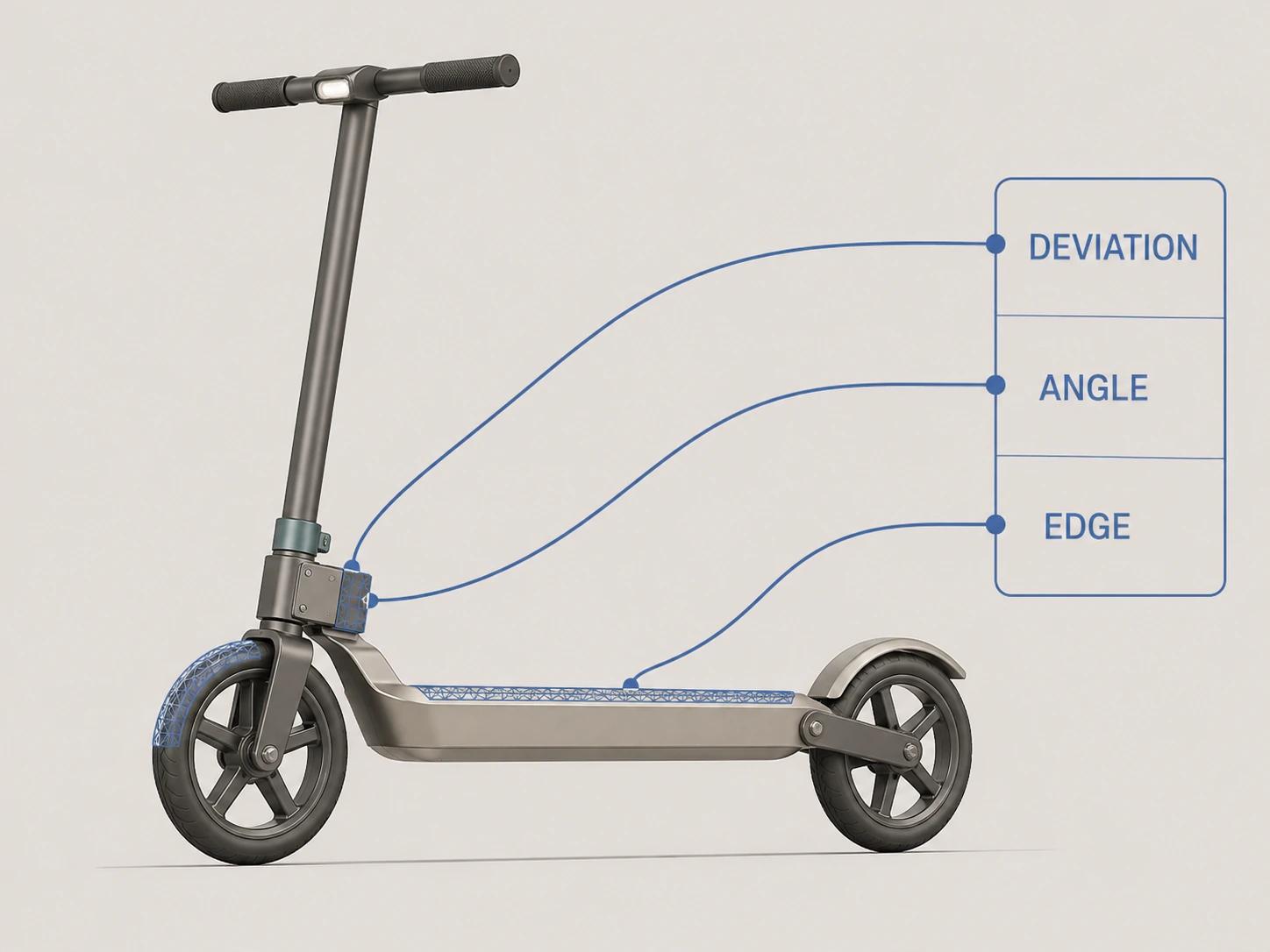
Tessellation samples CAD surfaces into polygons. The useful controls are tied to shape error, not a fashionable triangle count. Autodesk's VRED import documentation exposes chord deviation, normal tolerance, maximum chord length and stitching tolerance, alongside choices about imported surfaces, source data, normals, geometry merging and transforms.[2] Different software uses different names, but the decisions are recognizable:
- Chord or surface deviation limits how far the polygonal approximation may depart from a curved source.
- Normal or angular tolerance controls how closely the mesh follows changes in surface direction.
- Maximum edge length can force more samples across broad or shallow features.
- Stitching tolerance affects whether adjacent surface patches share a clean boundary.
Lower deviation is not automatically better. It can flood flat or unseen areas with triangles while leaving downstream material, hierarchy or device problems untouched. Begin with the views and features that matter: silhouette, wheel arcs, thin gaps, bevel highlights, interface openings, engraved artwork and any joint that moves. Generate a comparison render from the source and tessellated result under neutral grazing light. Tighten settings locally or by part where the acceptance view exposes faceting.
Never publish a bare tessellation preset as a universal requirement. State the source scale, views, largest expected on-screen size and visible-error threshold. If a five-metre product and a five-centimetre product use the same numeric chord setting without unit context, the setting says almost nothing.
Cleanup removes conversion debris; retopology changes the mesh
Cleanup should preserve approved form while removing defects or baggage. Typical work includes deleting isolated and internal elements that are out of scope, resolving duplicate faces, fixing unintended holes, orienting normals, welding only intended seams, applying or rationalizing transforms, restoring useful names and separating parts that must move or change material.
Do not merge by habit. One mesh may reduce scene complexity, but it can destroy pivots, variant addressability or reusable instances. Do not weld a designed panel gap because two boundaries happen to sit close together. Keep a cleanup log with before-and-after part counts, named removals and any tolerance used by a repair operation.
Retopology is a reconstruction step. Autodesk describes its retopology tools as creating a clean quad-based mesh from high-resolution input and recommends checking malformed data, holes, spikes, isolated elements and normals around the operation.[3] For web product work, use it selectively when the tessellated mesh has long slivers, unstable shading, poor deformation, unmanageable editing, or more density than the visible shape requires.
Retopology does not certify fidelity. The new surface is an artist- or algorithm-made approximation, so project key edges and compare it back to the controlled source. Preserve sharp breaks, circular openings, mating seams and the silhouette before chasing evenly spaced polygons. If the product stays rigid and the original tessellation shades cleanly, targeted reduction and normal repair may be safer than a complete rebuild.
Fine manufactured detail often becomes a geometry-versus-texture decision. Build a comparison for shallow embossing or relief: geometry on one side and baked detail on the other, reviewed in the accepted views at the silhouette, grazing angles, shadows and interactions. Keep geometry wherever the baked version fails the project criteria; approve baked detail only after reviewers accept that boundary.
UVs and materials are usually rebuilt for the target renderer
CAD color assignments are useful clues, not finished web materials. The glTF specification defines a material as a parameterized approximation of visual properties and defines meshes, materials, textures, normals, tangents and texture coordinates as separate parts of the runtime asset.[5] A source label such as "anodized black" does not by itself supply a portable base color, metallic response, roughness, normal detail or opacity behavior.
UV unwrapping maps a three-dimensional surface onto two-dimensional image space. Blender's manual describes UV points, edges and faces as counterparts of mesh vertices, edges and faces, and recommends a test image to reveal distortion before final texture work.[4] For a converted product, inspect:
- stretch on logos, brushed grain, fabric weave and other directional detail;
- seams in hero views and across mirrored parts;
- overlaps, deciding which are deliberate and which corrupt unique baking;
- consistent texel density where equal detail is expected;
- padding between islands so lower-resolution mip levels do not bleed;
- the exact UV set used by every texture and destination.
Khronos's current real-time asset guidelines explain that glTF uses triangles, that vertex splits can occur where texture coordinates or normals differ, and that UV island contact can cause visible bleed under mip mapping. They also describe metallic-roughness materials, texture baking and the trade-off between geometry, texture detail and runtime cost.[6] This is why triangle count before export is not the whole cost: seams, hard normals and material boundaries can increase the vertex data the renderer receives.
Build a small material reference sheet under agreed neutral lighting. Approve identity, not identical pixels across renderers. Then compare the exported GLB in the destination lighting with the approved reference. Record differences in extension support, image-based lighting or transparency handling as destination-specific findings rather than assuming parity.
Optimization and LODs need a destination budget
Optimization is a negotiation among silhouette, material readability, transfer size, decode work, GPU memory, draw calls and interaction. Treat geometry and textures separately. Remove unseen detail, reuse genuinely repeated geometry, combine material zones only when variant control allows it, and reduce texture resolution according to the closest accepted view. If compression is proposed, test the exact compressed export and record its transfer size, decode behavior, extension support and visual result instead of reporting only a percentage from the authoring tool.
glTF is a runtime delivery format, not an authoring format, and it does not mandate runtime behavior.[5] Keep the editable DCC master, source references, bake inputs and export recipe outside the delivery GLB.
Level of detail can mean separate destination exports or several representations that a supported runtime switches by screen coverage or distance. The MSFT_lod vendor extension can describe geometry or material LODs, but its own documentation says a client that does not implement the extension loads the highest level and ignores the lower ones.[7] Do not add LODs until the destination confirms how it discovers, selects and downloads them. Multiple embedded levels can make a file heavier without improving an unsupported viewer.
A useful budget names a scenario. "Under 8 MB" or "60 fps" is incomplete without the exact file, cache state, browser version, device, viewer, network and camera path. Record cold and repeat loads separately. Measure first render and sustained interaction, then inspect whether the chosen threshold preserves the product at the closest accepted view.
Define the acceptance profile before testing
The values below are a worked specification for one hypothetical scooter asset, not measured results or universal targets. Replace every value with the product and destination owner's criteria before production.
| Profile field | Worked assumption | Worked acceptance threshold |
|---|---|---|
| Tested file | FOLD-SCOOTER_R17_WEB_R03.glb, self-contained GLB derived from STEP assembly R17 | File checksum and source revision match the inspection record |
| View envelope | Product-page orbit, 25 cm closest virtual camera distance, folded and open states | No silhouette steps, open seams or missing sellable parts in six named views at twice intended display size |
| Dimensional control | Overall length, deck width and wheel diameter supplied by product owner | Each sampled dimension within the owner's project-set 2 mm tolerance |
| Desktop condition | Current stable Chrome, Windows laptop, integrated graphics, exact versions captured at test time | First usable render within 4.0 seconds on an empty cache; orbit remains at or above 30 fps for the scripted 20-second path |
| Mobile condition | Current stable Chrome on the named mid-range ARCore Android phone, exact OS and hardware captured | No crash, texture substitution or sustained period below 24 fps on the same path |
| Network condition | 10 Mbps downstream, 100 ms round-trip latency, empty HTTP cache | Transfer and first-render threshold met in three repeated cold runs; report all three, not only the fastest |
| Conformance | Exact exported GLB in the Khronos glTF Validator | Zero errors; every warning reviewed and dispositioned |
| Destination release | Exact ingested asset in each intended viewer | Product, controls, variants, material identity and measured performance meet that destination's separate record |
The thresholds are deliberately attached to a file and conditions. A luxury watch close-up, room-scale sofa, animated machine and configurable shoe need different view envelopes and may justify different geometry, texture and timing budgets.
Use this CAD-to-GLB inspection checklist
This is an original Double Edged checklist. Attach evidence to each box; a tick without a file, screenshot, report or named reviewer is weak release evidence.
- [ ] Identity: The GLB checksum, source CAD revision, configuration, units and export recipe are recorded.
- [ ] Source completeness: Missing references, suppressed parts, hidden geometry, variant rules and CAD-to-as-sold differences are resolved or logged.
- [ ] Tessellation: Chord, angular, edge-length and stitching settings are recorded with source units; named close-up views pass the profile's visible-error threshold.
- [ ] Product geometry: Controlling dimensions, silhouette, gaps, moving boundaries and visible part inclusion pass against approved evidence.
- [ ] Mesh health: Normals, winding, duplicate faces, isolated elements, unintended holes and non-manifold areas are inspected; every repair has a reason.
- [ ] Hierarchy and transforms: Origin, scale, up direction, pivots, repeated components and animation states work in the exported file, not only in the DCC scene.
- [ ] Retopology and baking: Rebuilt zones are listed and compared with the source; baked details remain acceptable at the closest view and grazing angles.
- [ ] UVs: Stretch, seams, overlap, texel density, island padding and texture-set assignment pass with a diagnostic grid and final maps.
- [ ] Materials: Every sellable finish maps to an approved reference; metallic, roughness, normal, opacity and extension behavior are checked in neutral and destination lighting.
- [ ] Packaging: The selected self-contained GLB has no missing external resource dependency, unused payload or accidental internal component.
- [ ] Specification: The exact delivery file is checked with a glTF validator. Khronos's browser validator performs validation locally and does not upload the submitted asset.[8]
- [ ] Performance: Cold and repeat loading, decode, first render, memory symptoms and the scripted interaction path are measured under the acceptance profile.
- [ ] Destinations: The Online store, Shopify, Product customizer and Android AR records are separate; one result is not copied into another.
- [ ] Release: Product, visual, technical and destination owners accept the immutable file revision, with exceptions and retest triggers recorded.
Inspect the GLB locally, then prove each destination
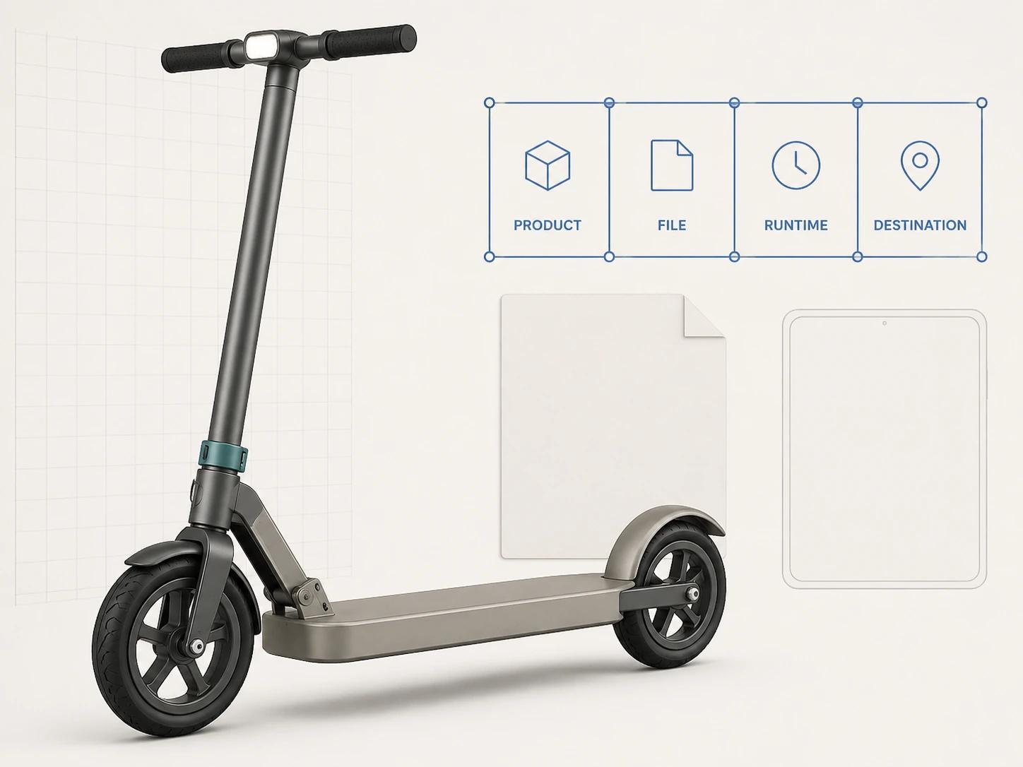
The Private GLB Readiness Checker inspects and previews a selected self-contained GLB locally in the browser; the selected GLB remains local.[11] It reports exactly four separate destinations: Online store, Shopify, Product customizer and Android AR. Browser preview does not prove destination compatibility or performance. The optional editable Excel QA workbook is secondary; use it when a team needs to carry owners, evidence and acceptance decisions beyond the browser session.
A Shopify result still needs the active store and theme checked. Shopify's current documentation accepts GLB as product media, requires a supporting theme and describes platform optimization for uploads above its stated threshold.[9] An Android AR result still needs a supported device and live launch path; Google's Scene Viewer documentation lists device, operating-system and service requirements and provides fallbacks when AR is unavailable.[10] Those are destination facts, not properties a desktop preview can certify.
Brief 3D CAD conversion services around evidence
Ask a supplier to estimate translation, reconstruction and optimization separately. Supply one representative assembly and require a pilot through the full acceptance profile before scaling to a catalog. The brief should name permitted omissions, required moving parts, variants, target views, material references, editable masters, delivery files, destination tests and change ownership.
Require a conversion log and rebuilt-zone register. If security, capacity and supplier controls are also part of the decision, use 3D Modeling Outsourcing: How to Evaluate Quality, Security and Scale rather than forcing those questions into a mesh checklist.
When a controlled CAD source needs a reusable visualization master and tested destination derivatives, the web-ready and AR-ready 3D service can scope the translation, rebuilding and measurement work. Bring the source revision, intended interactions, representative product, destination list and acceptance profile.