A useful 3D product model is accurate for a stated purpose. That purpose might be a close product render, a family of color variants, an assembly animation or a real-time product view. Those jobs do not require identical source evidence, geometry, materials or handoff files.
The practical way to scope 3D product modeling is to define four things before production starts: the decisions the model must support, the evidence available to build it, the features that must be verified, and the deliverables each downstream team will receive. "High quality," "photoreal" and "web ready" are not substitutes for those decisions.
This guide provides usable input, accuracy and deliverable tiers. They are Double Edged editorial frameworks, not engineering standards. They deliberately contain no universal polygon counts, texture sizes, dimensional tolerances or file-format guarantees. Those values belong in a product- and destination-specific acceptance plan.
Start with the decision the model must support
A model should be specified against its highest approved use, not against the most ambitious use someone might imagine later. A mid-distance campaign render may need a convincing silhouette and materials but no operable internals. An exploded animation needs a dependable part hierarchy and plausible separation paths. A configurable product family needs stable component boundaries and a variant map. A destination-specific interactive model needs a separate runtime handoff.
Write the intended decisions as observable statements:
- A product owner can approve the visible housing shape, controls and finish zones against named sources.
- A renderer can frame the approved closeups without exposing unresolved geometry.
- A motion artist can move the named parts around approved pivots without rebuilding the assembly.
- A commerce team can select valid finish or component combinations from a controlled variant list.
- A delivery team can create and test a derivative for its named runtime destination.
Use this framework once the product definition is sufficiently settled to model. If the team is still deciding form, features or engineering intent, start with the separate guide to product design 3D modeling from concept to commerce asset. A visualization model can expose a missing decision, but it should not quietly make that decision and present the result as approved product truth.
Use an input-evidence ladder
Source files should be ranked by what they can prove. A large folder is not necessarily a strong brief, and a CAD-shaped file is not automatically complete. NIST describes STEP as an ISO 10303 exchange format that can represent parts, assemblies and Product and Manufacturing Information. It also distinguishes computer-interpretable semantic PMI from graphic PMI that preserves the visual appearance of annotations.[1] The useful question is therefore not just "Do we have STEP?" but "What product definition does this particular file contain, at which revision, and what survived export?"
The following input bands are a Double Edged editorial framework. They describe evidence strength, not guaranteed output quality.
| Input band | Typical evidence | What it can reasonably control | Gaps to record |
|---|---|---|---|
| E1: visual reference | Dated multi-angle photos or video, approved marketing imagery, product ID, one or more reliable overall dimensions, finish names | Visible identity, broad silhouette, component presence, finish zoning and the intended visual condition | Hidden surfaces, lens distortion, exact curvature, interfaces, wall thickness, internal construction and any dimension not supplied |
| E2: dimensioned product reference | E1 evidence plus released drawings or usable CAD, declared units, revision, key dimensions, orthographic views, part list and material or finish schedule | Proportions, named features, repeatable camera comparisons, component boundaries and selected dimensions | Missing tolerances or datums, suppressed parts, stale variants, export losses, incomplete artwork and undocumented manufacturing changes |
| E3: controlled engineering evidence | Released native CAD or validated exchange, applicable PMI or drawings, units, revision state, datum and tolerance scheme where relevant, change authority and inspection evidence for critical features | The specifically named dimensions, interfaces and relationships that the product authority has approved for verification | Any feature outside the controlled definition, translation behavior, manufacturing variation and whether the visualization model is authorized for engineering use |
Build a source-of-truth register
For every received item, record its owner, product or variant ID, revision, units, date, intended authority and known exclusions. Mark one source as controlling for each disputed attribute. The latest photograph may show current artwork while the released CAD controls geometry. A physical sample may resolve a seam treatment while an approved finish schedule controls the customer-facing color name.
Do not average contradictions. If a drawing, sample and photograph disagree, log the conflict and ask the product authority to resolve it. Until then, show the affected feature in an assumption register and keep it out of final approval. This is more useful than burying the choice in a modeling comment that no reviewer sees.
Photographs are strongest when they are planned: consistent product state, enough views to reveal the form, detail coverage for graphics and seams, and an object or measurement record that establishes scale. Without controlled measurement provenance, treat a photograph as visual evidence rather than a dimensioned definition. A single overall width does not prove every radius, gap and recess.
Material inputs need the same discipline. Collect finish IDs, approved swatches or measured references where available, artwork files, application scale, orientation, repeat behavior and a list of which parts receive each finish. A color name alone does not specify surface response. For material approval, name the review setup, light and display conditions so reviewers judge against a defined setup instead of expecting identical pixels everywhere.
Choose an accuracy level by attribute
"Accurate model" is too broad to accept or reject. Accuracy should identify the attribute, its controlling source, the comparison method, the permitted deviation or decision rule, and the reviewer. The housing silhouette can be approved while a rear mounting interface remains unresolved. One status for the entire model would hide that difference.
ASME Y14.5 establishes symbols, rules and practices for stating and interpreting geometric dimensioning and tolerancing on engineering drawings, digital models and related documents.[2] A commerce model does not inherit engineering authority merely because it resembles the CAD. If engineering fit, function or interchangeability matters, the relevant product authority must supply the applicable definition and own acceptance.
Use these Double Edged editorial accuracy levels to make the intended review explicit:
| Accuracy level | Appropriate purpose | Minimum acceptance evidence | What it does not authorize |
|---|---|---|---|
| A1: visual-conformance | Mid-distance renders, early shot planning and presentations where visible identity is the decision | Approved view set, silhouette overlay at named cameras, component checklist, finish-zone review and an open-assumption list | Dimensional claims, fit checks, manufacturing decisions or unseen-feature approval |
| A2: proportion-controlled | Multi-view product imagery, closeups and reusable visualization where repeatable shape relationships matter | A1 evidence plus units, reliable overall and selected feature dimensions, orthographic or CAD comparison, named closeup views and pass/fail notes | Unspecified tolerances, interface validation or a claim that every surface matches production CAD |
| A3: selected-feature controlled | Assembly animation, variant systems or marketing assets where named interfaces, gaps, pivots or component boundaries must agree | A2 evidence plus a controlled feature list, source revision, per-feature comparison method, supplied acceptance thresholds and product-owner sign-off | Engineering release, inspection certification or accuracy for features absent from the controlled list |
| A4: engineering-defined for stated features | A downstream use that genuinely depends on product-defined geometry and tolerances | Released engineering definition, applicable dimensions and tolerances, units and datums, translation checks, measurement method, uncertainty where relevant, and approval by the responsible engineering authority | A blanket claim that the visualization asset is manufacturing-ready or suitable for every engineering decision |
The framework supplies no default millimeter threshold. A hinge axis, cosmetic seam and soft upholstery contour do not share one sensible tolerance. The product authority should provide the threshold or decision rule for every controlled feature, and the production team should confirm that the supplied evidence can support it.
Keep "traceable" precise
A model can have document traceability without having metrologically traceable dimensions. Document traceability means the team can follow a feature back to a file, revision, decision and approver. NIST defines metrological traceability more narrowly: a measurement result relates to a reference through a documented unbroken chain of calibrations, with each calibration contributing to measurement uncertainty.[3] NIST also places responsibility on organizations for establishing the traceability of their own results.
Use "source-traceable" for a clean revision and approval chain. Use "metrologically traceable" only when the measurement process actually meets that definition. Neither phrase alone proves fitness for a use. The acceptance plan still has to say which feature matters and how accurate the result must be.
Specify the deliverable ladder from render to real time
A final render is not a reusable model handoff. A source scene is not automatically a destination asset. The following model-specification ladder is an original Double Edged editorial framework for choosing what the project should leave behind.
| Deliverable tier | Primary use | Package contents | Acceptance focus |
|---|---|---|---|
| D1: render-specific model | Produce the approved views for one defined image or motion scope | Working geometry, materials needed for the approved shots, scene dependencies, review renders and documented off-camera limitations | The named cameras, frames and visible product attributes pass; exclusions are explicit |
| D2: reusable visualization master | Support new studio views, later campaigns or additional motion within an agreed visual envelope | Organized source geometry, sensible part separation, reusable materials, texture sources, naming, scale and orientation record, clean neutral review scene, version manifest and D1 outputs | Approved view envelope, source completeness, reload test, material assignment, hierarchy and editable handoff |
| D3: variant-ready commerce master | Generate governed product, component and finish combinations across channels | D2 package plus variant matrix, stable component and material IDs, option dependencies, artwork mapping, default state, invalid-combination rules and representative variant tests | Every approved option resolves to the intended geometry and material state without silent combinations |
| D4: destination-specific real-time derivative | Feed one named viewer, configurator, app or platform after a separate conversion and test scope | Derivative geometry and materials, packaged textures, declared units and orientation, destination format, build record, runtime preview, limitation log and acceptance report | The exact file is tested in the named destination and conditions against that destination’s criteria |

The tiers are not automatic maturity stages. A project can need D3 without D4. A D4 asset may be rebuilt from a strong source rather than obtained by pressing Export on D2. Detailed tessellation, retopology, UV rebuilding, texture baking, level-of-detail policy and runtime performance acceptance belong in CAD to Web 3D: What Gets Converted, Rebuilt and Optimized. Here, D4 marks the contractual boundary: name the destination and require a tested derivative.
Treat file formats as package roles
Ask for roles before extensions:
- The editable authoring source preserves the structure the production team needs to revise.
- An interchange copy serves an identified receiving application or archive workflow.
- A destination derivative meets the technical contract of one approved channel.
- Human-readable previews, manifests and QA records explain what each file is and what passed.
The formats may differ because they carry different kinds of data. STEP is used for exchanging product geometry and manufacturing information among CAD and downstream systems, while its PMI can be semantic, graphical or absent in a particular file.[1] OpenUSD can describe geometry, shading and other scene data, and its composition system supports layers, references and variants for content-creation pipelines.[6] Those capabilities are useful when the chosen tools consume them correctly; they are not evidence that every recipient, exporter or platform preserves every property.
glTF 2.0 has its own explicit runtime conventions. Its specification defines a right-handed coordinate system, meters for linear distance, mesh and material structures, and a GLB container that can package the JSON and a binary buffer in one file.[5] That makes units and packaging inspectable. It does not prove the product is correctly scaled, the materials match a render master or a specific destination accepts the asset. Those remain QA questions.
Name the application and version for the editable source; the required extension and version for each exchange or destination file; the unit and axis expectations; what must remain editable; how textures are linked or packed; and which features may be flattened. Require the recipient to reopen or ingest representative files before the package is accepted.
Define geometry, materials and variants separately
Geometry acceptance should cover only what the use needs: silhouette, proportions, visible construction, closeup features, component splits, pivots and controlled dimensions. Record purposeful simplifications. Removing an unseen internal fastener may be reasonable for a render master, but deleting a removable battery would be wrong if the animation must show it.
Material acceptance needs a material-zone map, approved references, surface behavior under a neutral review light, and texture-source ownership. UV mapping assigns 2D texture information to mesh faces, and Blender’s official manual recommends checking mapping with a test grid when stretching matters.[4] A delivery should therefore state which objects require UVs, which map is active, how distortion is reviewed, where the texture files live, and whether procedural materials have been converted for the receiving use.
Variant acceptance is a data problem as much as a visual one. Give every option a stable ID and map it to geometry, materials, artwork and availability rules. Separate finish changes from construction changes. A black housing and a white housing may share geometry; a different sensor layout, mounting plate or button arrangement probably should not be treated as a color swap. Test one ordinary combination and the combinations most likely to reveal missing dependencies.
Run a six-stage production and review workflow
This workflow is another Double Edged editorial recommendation, designed to keep assumptions visible.
1. Brief the use and evidence
List deliverable tier, accuracy level by attribute, required views or interactions, variants, destination, source owners and reviewers. Build the source-of-truth register before modeling. Reject corrupt or ambiguous inputs early rather than pricing certainty around them.
2. Issue a gap and assumption report
Compare the requested acceptance criteria with the evidence. Mark missing views, dimensions, parts, artwork, finishes, revisions and destination details. Give each assumption an owner and due date. State which work can proceed safely and which approval is blocked.
3. Approve a blockout
Review overall scale, orientation, silhouette, major components and the controlled proportions before small details or finished materials absorb time. Use the named cameras and overlays from the acceptance plan. A blockout pass approves a limited geometry state, not the final product.
4. Resolve detail, materials and variants
Add only the detail required by approved views and downstream reuse. Review geometry and material evidence separately. Then exercise representative variants against stable IDs and rules. Any source change gets a new revision entry and a stated impact on prior approvals.
5. Perform technical and product QA
The modeler checks scene health, dependencies, naming, transforms and package completeness. The product authority checks the controlled product attributes. The destination owner checks the actual derivative where D4 is in scope. Keep those decisions separate even when one person holds several roles.
6. Package and reopen
Deliver into a clean folder or managed asset location, then reopen the source and ingest representative exchange files in the intended receiving environment. Record missing links, substitutions and import warnings. Approve immutable package IDs or checksums so later edits cannot inherit an earlier sign-off unnoticed.
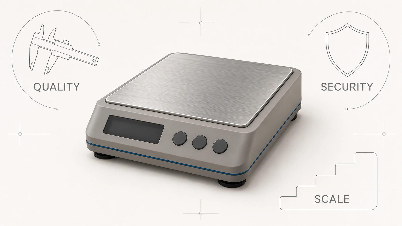
If an outside studio will own these steps across many products, the companion guide to evaluating 3D modeling outsourcing for quality, security and scale covers supplier controls rather than repeating this model specification.
Use this 3D product modeling quality checklist
- [ ] The model’s approved uses and explicit non-uses are named.
- [ ] Each requested attribute has an accuracy level, controlling source, comparison method, decision rule and reviewer.
- [ ] Every input records product ID, owner, revision, units, authority and known exclusions.
- [ ] Conflicting sources appear in an assumption register instead of being silently blended.
- [ ] The geometry review covers the silhouette, view envelope, visible construction, named features, part splits and pivots that the use requires.
- [ ] Any dimensional threshold comes from the product authority; the brief does not invent a universal tolerance.
- [ ] Material zones, finish IDs, artwork, UV requirements, texture files and neutral review conditions are documented.
- [ ] Variant IDs map to controlled geometry, material and artwork states, including invalid combinations where relevant.
- [ ] The deliverable tier states what is editable, reusable, destination-specific or excluded.
- [ ] Native source, interchange files, runtime derivatives, previews, manifests and QA evidence have distinct roles.
- [ ] Representative files reopen or ingest in the named receiving environment.
- [ ] Product, production and destination approvals attach to a fixed package revision.
- [ ] Rights, permitted reuse, third-party dependencies, retention and future-update responsibilities are stated.
A well-scoped package does not claim more accuracy or portability than its evidence can support. It gives the next team enough structure to use the model, enough evidence to review it, and enough boundaries to know when a new conversion, measurement or modeling task is required.
Bring the evidence and intended outputs into scope
When you have an approved product, source evidence and a defined set of render, animation, variant or downstream asset needs, the 3D product modeling service can turn that scope into a production plan. Share one representative product, the available source register, required accuracy by attribute and intended deliverable tier so the unknowns can be separated from the build.