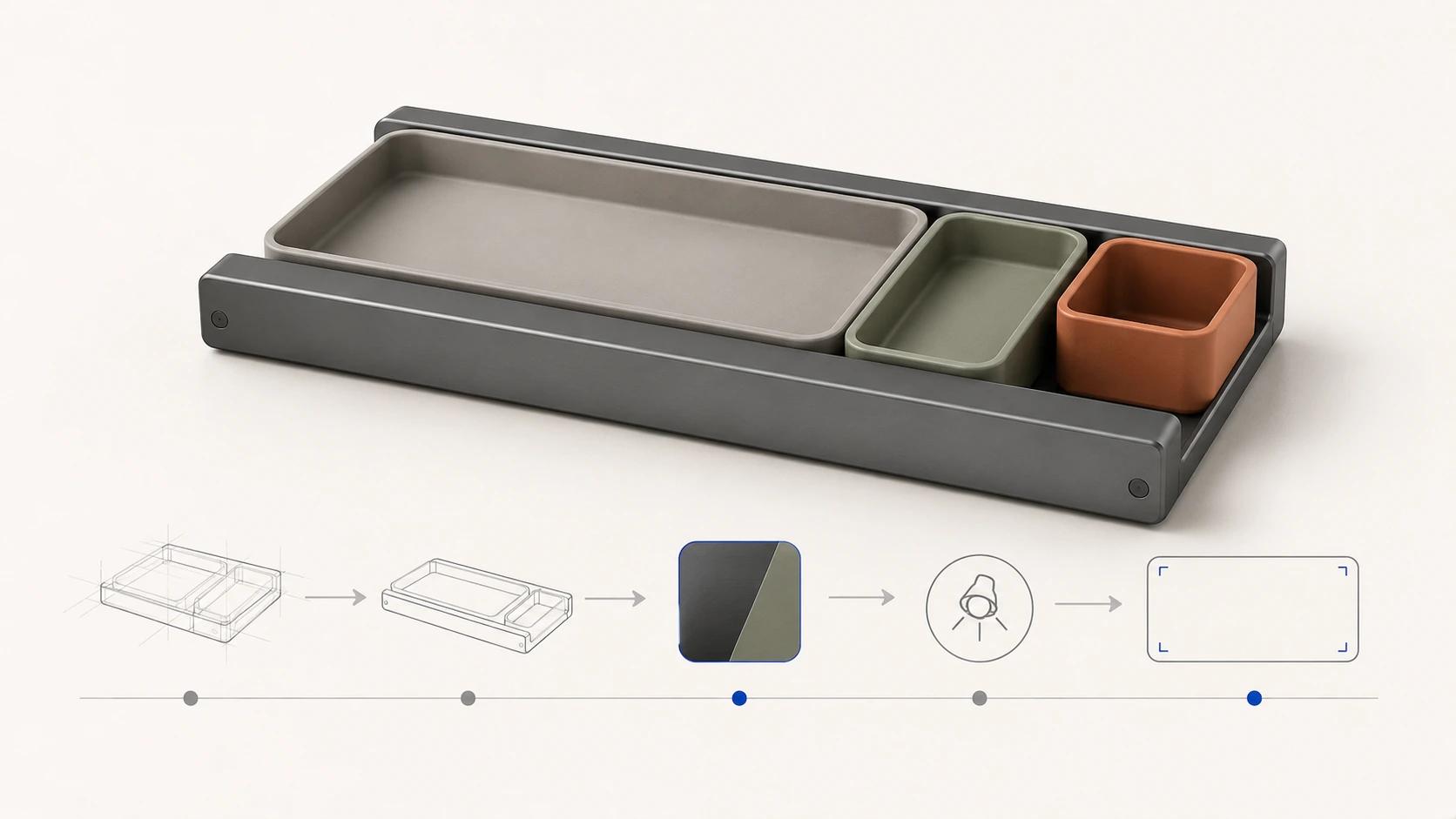
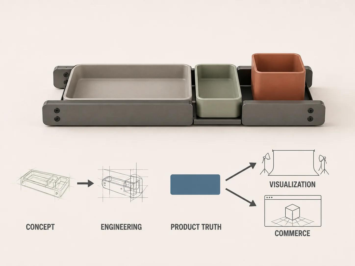
Product design 3D modeling should not depend on one file being passed from designer to engineer to rendering artist and then uploaded to a store unchanged. The safer workflow is a controlled lineage: exploratory concept geometry informs an engineering definition; an approved product-truth baseline controls what may be shown; a visualization master translates that truth for image-making; and channel-specific commerce assets are derived and tested for their destinations.
Each state answers a different question. The concept model asks what the product could become. Engineering data defines how the intended product is constructed and specified. The visualization model decides how approved form and materials will be represented on camera. A commerce asset packages that representation for a particular page, viewer, animation or configurator. Calling all four "the 3D model" hides the handoff decisions that matter.
Use this workflow while concept and engineering decisions are still moving toward a controlled commerce baseline. If the product definition is already settled and the task is to choose source inputs, accuracy levels and deliverables, use the broader guide to 3D Product Modeling: Inputs, Accuracy Levels and Deliverables.
Treat the handoff as model lineage
An engineering exchange file can carry more than a visible shape. NIST describes STEP files as representations of parts, assemblies and Product and Manufacturing Information used across CAD, manufacturing, analysis and inspection software. It also distinguishes semantic PMI, which downstream software can interpret, from graphic PMI that preserves the appearance of annotations.[1] A smooth viewport preview does not tell a recipient which of that information is present, current or controlling.
Geometry types also have different jobs. NIST describes facet data as triangular meshes that approximate surfaces, while precise boundary-representation geometry defines closed volumes mathematically for high-precision uses such as engineering analysis, manufacturing and inspection.[2] Hybrid engineering workflows can combine those representations, but that does not make every polygon mesh an engineering model.
A visualization mesh can be faithful in approved views and still omit tolerances, datums, wall construction, fasteners, hidden interfaces or analytical properties. That is not a defect when those exclusions are deliberate. It becomes a defect when the derivative loses its provenance and is later treated as the released definition.
In this article, product truth means the controlled package a named product authority has approved for the representation task. It is an original editorial term, not a claim that one standard file contains the whole truth. Depending on the product, the package may combine released CAD, drawings or PMI, part and variant records, finish references, artwork, approved physical samples, deviations and an open-issue register.
Use a five-stage product design 3D modeling workflow
The following stage table is an original Double Edged framework. Stages can overlap, and a team may use several tools inside one stage. The gate is the decision, not the software or extension.
| Stage | Working model or package | Decision it supports | Minimum handoff evidence | What it does not prove |
|---|---|---|---|---|
| 1. Concept intent | Sketch models, rough CAD, subdivision surfaces, appearance studies and provisional CMF | Which form, layout and product direction should advance | Named concept revision, intended scale, key views, unresolved assumptions and design-owner decision | Manufacturability, production dimensions, tolerances or final materials |
| 2. Engineering definition | Native CAD, assemblies, drawings, applicable PMI, calculations and controlled requirements | How the selected design is specified, assembled, analyzed and released | Units, revision, part structure, controlling dimensions and interfaces, change owner, verification and validation plan or status | That an exported mesh retains engineering meaning or that the physical product has passed every test |
| 3. Product-truth baseline | Approved engineering release plus as-sold variant, finish, artwork and deviation records | What the visualization is authorized to represent at a stated date | Baseline ID, source register, conflicts resolved or logged, approved configuration and product-owner sign-off | Future changes, undocumented factory substitutions or channel compatibility |
| 4. Visualization master | Organized DCC geometry, render materials, texture sources, hierarchy, cameras and a derivation log | How approved product truth will be represented across agreed visual uses | Derived-from baseline, dimensional spot checks, view envelope, simplifications, material references and review renders | Engineering release, physical performance or automatic fitness for a runtime destination |
| 5. Commerce asset family | Final stills, motion files, turntables, GLB or USDZ derivatives, and configurator-ready states | Whether each asset communicates the approved product and works in its named destination | Asset manifest, variant mapping, export record, destination test, limitations and release owner | Universal compatibility, identical rendering across devices or permission to change the product definition |
1. Explore concept without presenting it as release data
Early 3D work is allowed to be incomplete. Industrial and product designers may need to compare silhouette, proportion, interface placement, storage volume or a family resemblance before every seam and fastener is known. The model should make that uncertainty visible rather than polish it away.
Give the concept a revision and a decision statement: "review overall footprint and tray arrangement" is useful; "final model" is not. Mark provisional dimensions, placeholder components, assumed wall thicknesses and surfaces that exist only to communicate intent. If a render is used for an internal review, label its state in the review record so its realism is not mistaken for release authority.
The concept gate closes only for the decisions named in advance. Approval of the external form does not silently approve an internal structure. An attractive material study does not select a production finish unless the material owner says it does.
2. Let engineering own specification, verification and validation
The selected concept becomes an engineering input, not an engineering answer. Engineers may rebuild surfaces, define assemblies, add interfaces and fastening strategy, set material specifications, apply dimensions and tolerances, or change the form to satisfy requirements. Preserve a link back to the accepted design intent, but let the controlled engineering environment own those changes.
NASA defines product verification as objective evidence that an implemented, integrated, bought or reused end product conforms to specified requirements. Its listed methods include test, analysis, inspection and demonstration, all used within a planned process.[3] NASA treats validation separately: the verified end product is assessed against stakeholder expectations and intended use in its intended environment.[4]
That distinction matters well beyond aerospace. A rendering scene may help an engineer inspect a visible arrangement or communicate a proposed change, and a qualified analytical model may form part of a planned engineering method. A beauty-render mesh, material setup or smooth turntable does not by itself verify fit, strength, safety, tolerance, assembly or intended use. Rendering geometry never inherits those approvals from appearance alone.[2][3][4]
3. Freeze the product truth the asset is meant to show
Before detailed visualization, establish a baseline for the exact product and variants in scope. Record the released CAD or drawing revision, approved configuration, product and part IDs, customer-facing option names, finish assignments, current artwork, and any approved deviation between design data and the product that will be sold.
Resolve authority attribute by attribute. Engineering may control an interface; the product team may control the sellable variant list; brand may control current artwork; an approved sample may clarify a visible texture. When two sources disagree, do not blend them into a plausible compromise. Log the conflict, name its owner and block only the views or assets it affects.
The baseline also needs an effective date or release state. Commerce work often continues while engineering changes. A dated baseline tells reviewers whether they are approving the current production intent, an announced revision or a clearly labeled concept.
4. Derive a visualization master and record every exception
The visualization master is built for controllable visual production. It may use retopology, subdivision, renderer-specific shading, UVs, texture baking, presentation bevels, cleaned part splits or simplified off-camera geometry. Those choices can make the scene easier to light, animate and reuse. They can also create distance from the engineering source.
Start the derivation log while converting, not after approval. Record the source baseline, units, coordinate orientation, tessellation settings, rebuilt surfaces, omitted parts, exaggerated details, substituted materials and unresolved features. Keep product-facing IDs on objects and material zones where possible. A reviewer should be able to trace a visible housing, rail, tray or finish back to the approved source without reverse-engineering the scene hierarchy.
Review the master in two passes. Product review compares named visible attributes with controlling evidence. Visualization review checks topology, smoothing, UV behavior, shading, hierarchy, pivots, dependencies and the agreed view envelope. A pass in one review does not imply a pass in the other.
Decide each handoff with evidence
This decision table is another original Double Edged framework. It prevents a vague "approved" status from following the model into uses that nobody reviewed.
| Gate | Decision owner | Evidence to inspect | Pass statement | Reopen when |
|---|---|---|---|---|
| Concept direction | Product or industrial design owner | Named views, scale, intent notes and assumption list | The stated form decisions may advance to engineering | The concept, intended use or major layout changes |
| Engineering release | Responsible engineering authority | Controlled requirements, CAD or drawings, interfaces and applicable V&V records | The named engineering definition is released for its stated configuration | A controlled requirement, part, interface or release changes |
| Product-truth baseline | Product authority with relevant engineering, brand and operations input | Source register, variant list, finishes, artwork, deviations and conflict log | The stated baseline may control the named visualization scope | Sellable configuration, artwork, finish, deviation or source revision changes |
| Visualization master | Product reviewer and visualization lead | Comparison views, derivation log, closeups, materials, hierarchy and open issues | The master represents the baseline within the approved visual envelope | A source change affects visible truth or a new view exposes excluded detail |
| Commerce release | Destination or channel owner | Exact export, manifest, variant mapping, previews and destination acceptance criteria | The exact asset revision may be used in the named destination | File, destination, theme, device requirement, variant data or approved presentation changes |
Build commerce assets as derivatives, not replacements
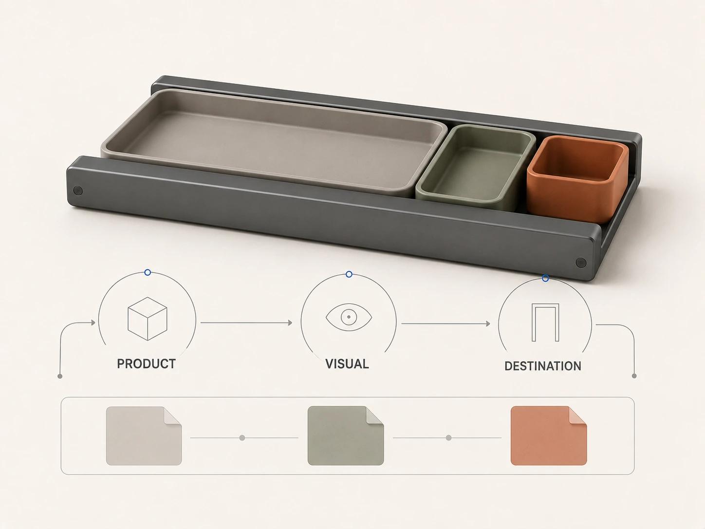
A commerce family can include still renders, image crops, product animation, a 360-degree sequence, an interactive model or configurable component and material states. They should share approved product identity, but they need not share one geometry file or material implementation.
Khronos defines glTF as a publishing and runtime-delivery format designed for efficient transmission and loading. A glTF or GLB can package scene structure, meshes, materials, textures and animation data.[5] That makes it a sensible derivative for many real-time uses, not a substitute for native CAD, released requirements or verification evidence.
The destination still controls acceptance. Shopify’s current product-media guidance accepts GLB and USDZ and describes platform conversion and, for larger uploads, optimization of geometry and textures.[6] A file that looks correct before upload may therefore enter another processing path. Test the exact asset after ingestion, record the destination and conditions, and keep visual parity separate from product accuracy and runtime performance.
Conversion may involve tessellation, cleanup, retopology, UV work, texture baking, material translation and optimization. Those details belong in the companion guide CAD to Web 3D: What Gets Converted, Rebuilt and Optimized. In the present workflow, the rule is simpler: every derivative points back to a product-truth baseline and forward to one named acceptance context.
Route changes back to the controlling owner
The lineage must work in both directions. Visualization often exposes collisions, missing parts, ambiguous seams or variant rules that looked harmless in a spreadsheet. Report the finding to the owner of the controlling source. Do not repair the marketing mesh and let that local edit become the only record of the decision.
Use five fields on every change: source baseline, affected attribute, proposed resolution, decision owner and downstream impact. If engineering changes the rail spacing, ask which visualization scenes, stills, animations, GLBs and configured states inherit it. If brand changes artwork only, avoid reopening unrelated geometry. If a commerce platform forces a material simplification, keep that exception on the destination derivative rather than pushing it back into product truth.
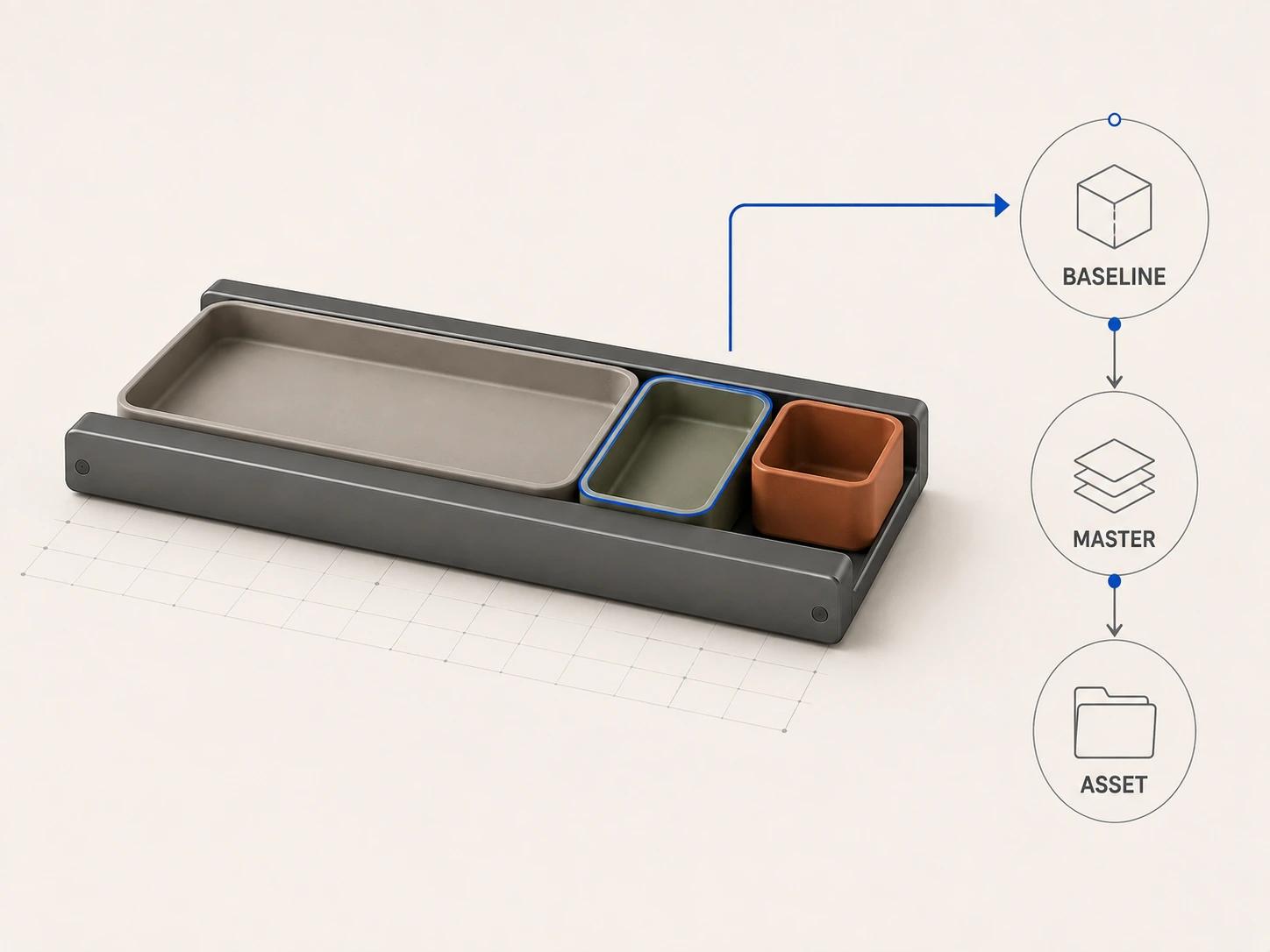
Assign immutable revision IDs to approved packages. A derivative should state "derived from baseline B17" rather than "latest CAD." When the baseline moves to B18, the asset owner can run an impact review and choose rebuild, targeted update, documented non-impact or retirement. None of those outcomes should happen silently.
Write product design 3D modeling requirements that can be tested
A useful brief names the decision and evidence instead of asking for a "production-ready master model." Include:
- the product, configuration and baseline revision to represent;
- the concept or released state, with unresolved assumptions listed;
- intended still, motion, interactive or configurable uses and the views they expose;
- controlling sources for geometry, visible construction, materials, artwork and variants;
- dimensions or interfaces that must be checked, with thresholds supplied by the responsible authority;
- permitted reconstruction, omission, exaggeration and material substitution;
- editable source, interchange and destination deliverables, each with a named recipient;
- the derivation log, source register, manifest and comparison evidence required at handoff;
- separate product, visualization and destination reviewers;
- change triggers, retention rules and downstream update ownership.
Reject phrases that carry no acceptance method: "exact," "optimized," "photoreal," "manufacturing ready" and "works everywhere." Each can become useful once it is tied to an attribute, destination, test and owner.
Use this quality checklist before commerce release
- [ ] The concept, engineering definition, product-truth baseline, visualization master and commerce derivatives have distinct IDs and owners.
- [ ] Every derivative names the exact baseline and configuration it represents.
- [ ] Conflicting sources are resolved by an authority or remain visible as blocking issues.
- [ ] Engineering verification and validation evidence is not inferred from render quality.
- [ ] Visualization changes, omissions and presentation adjustments are recorded.
- [ ] Product review covers the visible attributes and variants exposed by the approved views.
- [ ] Technical review covers scene health, transforms, scale, hierarchy, materials, textures and dependencies.
- [ ] Each commerce asset has a destination, export record, manifest and post-ingestion check where the destination permits one.
- [ ] Platform-specific simplifications stay on the derivative unless the product owner approves an upstream change.
- [ ] A baseline change triggers an impact decision for every active derivative.
- [ ] Approval attaches to an immutable revision, not a mutable folder called "final."
A disciplined lineage does not force designers, engineers and commerce teams into one tool. It gives each team the representation it needs while preserving who approved the product, what the asset claims to show and where its authority stops.
Bring a controlled baseline into production
When a concept or released product needs a traceable visualization master and a defined family of render, animation or commerce derivatives, the 3D product modeling service can scope the handoff around evidence rather than file extensions. Bring one representative configuration, the source register, current baseline, intended views and destination list.