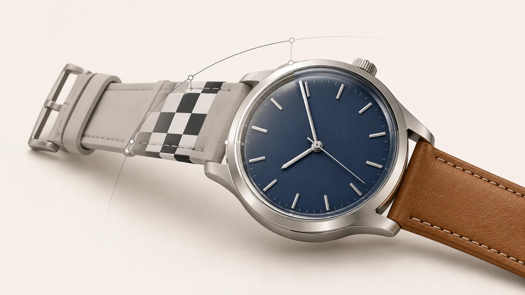
A photorealistic product model is not simply a dense mesh with high-resolution textures. It is a controlled asset whose silhouette, construction, edge transitions, shading normals, UV allocation and material response agree at the closest approved view. If the asset will support variants, motion or real-time use, its part structure and identifiers must also survive those later jobs.
That definition keeps the model separate from the finished image. Lighting, camera, color management and art direction still affect a render, but they belong to the companion guide on what creates realism in 3D product rendering. This page stays inside the asset: what photorealistic 3D product modeling services should build, inspect and hand off before a beauty scene can hide or flatter anything.
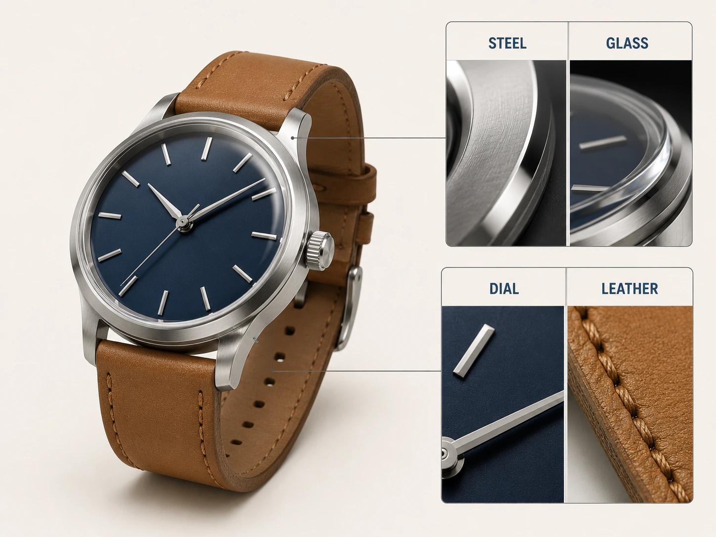
For the wider choices around source inputs, accuracy levels and deliverables, use 3D Product Modeling: Inputs, Accuracy Levels and Deliverables. Here, one brand-neutral analog wristwatch provides the test case: a brushed steel case, domed glass, navy dial and tan leather strap. Reflective metal, transparent glass, fine dial details and directional leather grain make weak decisions easy to see.
Use seven surface-evidence gates
The following is an original Double Edged studio framework, not an industry standard. It does not set universal tolerances. Each pass statement must inherit its evidence from the product, intended views and destination.
| Gate | Evidence on the wristwatch | Typical closeup failure | Pass statement |
|---|---|---|---|
| 1. Silhouette and scale | Case diameter and thickness, crystal dome, lug spacing, crown size, strap width | A plausible watch that does not match the approved product | Named views and dimensions agree with controlling references |
| 2. Construction | Separate case, bezel, crystal, dial, markers, hands, crown, spring bars, strap layers and buckle | Floating hands, paper-thin glass, fused seams or impossible overlaps | Visible parts meet, overlap and leave gaps as the product is intended to |
| 3. Edge behavior | Product-specific case breaks, bezel transitions, marker edges and leather cut edges | Razor highlights, inflated corners or melted transitions | Edges carry stable highlights without changing the approved form |
| 4. Normals and topology | Clean broad planes, controlled curved bands, predictable subdivision and triangulation | Wavy steel, pinched dome reflections or shading that changes on export | Diagnostic shading remains clean through required views and derivatives |
| 5. UV and texel plan | Distortion checks, seam map, material direction and view-priority allocation | Soft dial print, stretched leather grain or visible seams | Texture detail is allocated and oriented for the approved crops |
| 6. Material response | Distinct steel, glass, dial coating, hands, leather face, leather edge and stitching | Materials separated by color only or one noise pattern spread everywhere | Each zone responds according to its substrate, finish, scale and direction |
| 7. Reuse readiness | Stable names, pivots, material zones, variant mapping and derivative record | A beautiful master that cannot be animated, switched or exported safely | Planned still, motion and real-time derivatives can be made without losing identity |
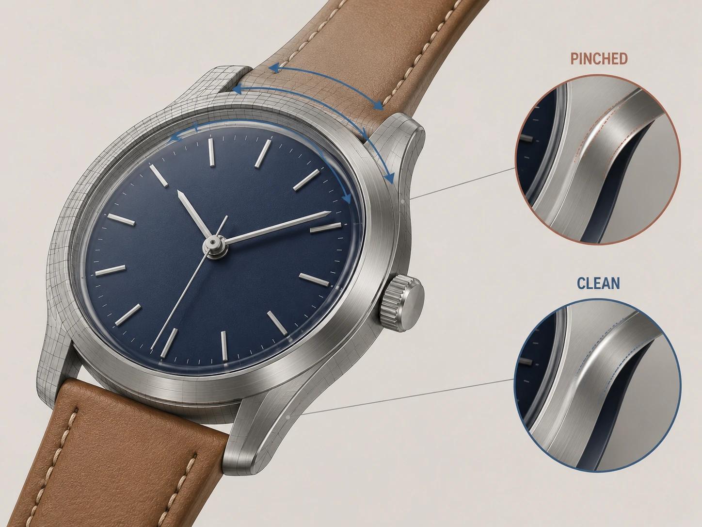
Treat the gates as a dependency chain. A normal edit can improve a broad steel face, but it cannot correct an oversized bezel. More texture resolution cannot recover a distorted UV island. A runtime export cannot infer which tan strap belongs to which product code. Review the earliest failed gate before polishing the later ones.
Build geometry for silhouette, construction and edge behavior
Start with the views and details that the approved asset must survive. A product-page hero may expose the case silhouette and lug spacing. A macro crop may reveal the crystal seat, dial-to-rehaut gap, hand stack and leather edge paint. Geometry outside that view envelope can be simplified deliberately; geometry inside it needs evidence.
Block the watch as separate manufactured parts before adding fine detail. This makes assembly logic reviewable. The domed glass needs visible thickness and a credible seat. Hands need a hub and vertical order rather than coplanar cards. The strap needs top leather, cut edge and underside only where those layers can be seen. A groove represented by a texture may be enough in a distant crop, while a crown tooth that breaks the silhouette may need geometry.
Edge behavior deserves its own approval. Blender's Bevel modifier documentation shows that a bevel is added geometry, with width interpretations, profile controls and a segment count that adds loops along the bevel face.[1] Those controls are mechanisms, not product dimensions. Set the case radius from CAD, drawings, measured references or an approved sample. Then choose enough segmentation for the closest view and output, rather than copying one modifier preset across the steel case, dial markers, buckle and leather.
Use a glancing specular diagnostic to inspect every important transition. The test should reveal whether a highlight flows around the case flank, breaks at the intended seam and stays quiet across a planar lug surface. If a corner only looks acceptable under one fixed camera, it is fragile. Check silhouette and reflection together.
Make normals support the form rather than repair it
Vertex normals affect whether shading appears soft or hard between polygon faces. Autodesk's Maya documentation explains that shared normal directions produce a soft transition, while normals aligned with their faces produce a hard, faceted transition.[2] This changes light interpolation. It does not move the surface.
For the watch, establish the physical break first, then decide how shading should cross it. The cylindrical case wall should read continuously around its circumference. A crisp boundary between the case and bezel may need a split. The top of a broad lug should stay visually flat even when a small bevel borders it.
Weighted normals are one possible tool. Blender can combine custom per-face-corner normals using face area, corner angle or both, and it can preserve marked sharp edges.[3] Use that behavior only after testing the unmodified mesh. Keep a normal visualization and a neutral reflective render in the review set. Imported, locked or custom normals can become stale when topology changes, so an edit to the bevel or part split should reopen the shading check.
A good rule is simple: normals may stabilize a highlight on valid geometry; they must not be used to disguise a wrong silhouette, missing thickness or broken intersection.
Choose topology for the behavior the part needs
There is no useful prize for making every product part all quads. Blender's mesh documentation distinguishes triangles, quadrangles and n-gons, and notes that quads deform well and suit subdivision workflows.[4] That supports a purpose-led decision, not a blanket rule.
Use topology according to five questions:
- Does it hold the silhouette at the closest approved view?
- Does subdivision preserve the intended planes, curves and edge spacing?
- Will the part deform, bend or articulate?
- Does triangulation remain predictable in the target renderer or exporter?
- Can another artist edit the part without unraveling local shading?
The static steel case can use a different strategy from a strap that may bend in animation. The domed glass needs smooth curvature and clean reflection flow; the dial can remain relatively simple but must support the marker and hand relationships. Place poles and density changes away from glancing reflective regions when they create visible pinching. A planar hidden cap may tolerate topology that would be risky on the polished bezel.
Review the cage, subdivided result and exported triangulation. Turn off textures and inspect the model under a broad moving highlight. If topology produces a wave in the brushed case or a dent in the crystal, adding scratches later will only make the defect busier.
Plan UVs as an image budget
A UV map projects the 3D surface into 2D texture coordinates. Blender recommends beginning the unwrap when only minor geometry adjustments remain because later face additions or subdivision can require extra mapping work.[5] That sequence reduces rework, but it does not mean waiting until every detail is final. Test representative parts early, then lock the production layout after the geometry gate.
Use a visible checker to judge stretch, seam placement and orientation. Put seams where a physical part break, hidden underside or low-priority view can absorb them. Preserve directional logic: brushed steel, radial dial finishing, leather grain and stitching cannot all be packed with arbitrary rotations if their textures rely on UV direction.
Adobe defines texel density as the number of texture pixels assigned to a given surface area. Higher density can retain more detail, while lower density may trade detail for performance; its guidance recommends consistency as a general baseline.[6] Consistency is a starting point, not a command to give every hidden surface equal space.
Use a Double Edged texel-budget ledger with these fields:
| Surface group | Closest approved crop | Detail that must resolve | Direction or seam constraint | Variant reuse | Intended derivative |
|---|---|---|---|---|---|
| Dial and markers | Front macro | Minute marks, finish breakup, marker edges | Radial orientation; keep face uninterrupted | Dial colors may change | Still and real-time |
| Steel case and bezel | Three-quarter closeup | Brush direction, machining transitions, edge response | Align directional finish; hide seams below | Shared across strap colors | Still, motion and real-time |
| Tan leather strap | Side and buckle detail | Grain scale, stitching, cut edge | Grain follows strap length | Color and finish variants | Still and motion |
| Hidden case back | Not in launch views | Only required identity or relief | Seam can sit out of view | May be shared | Preserve if later turntable is planned |
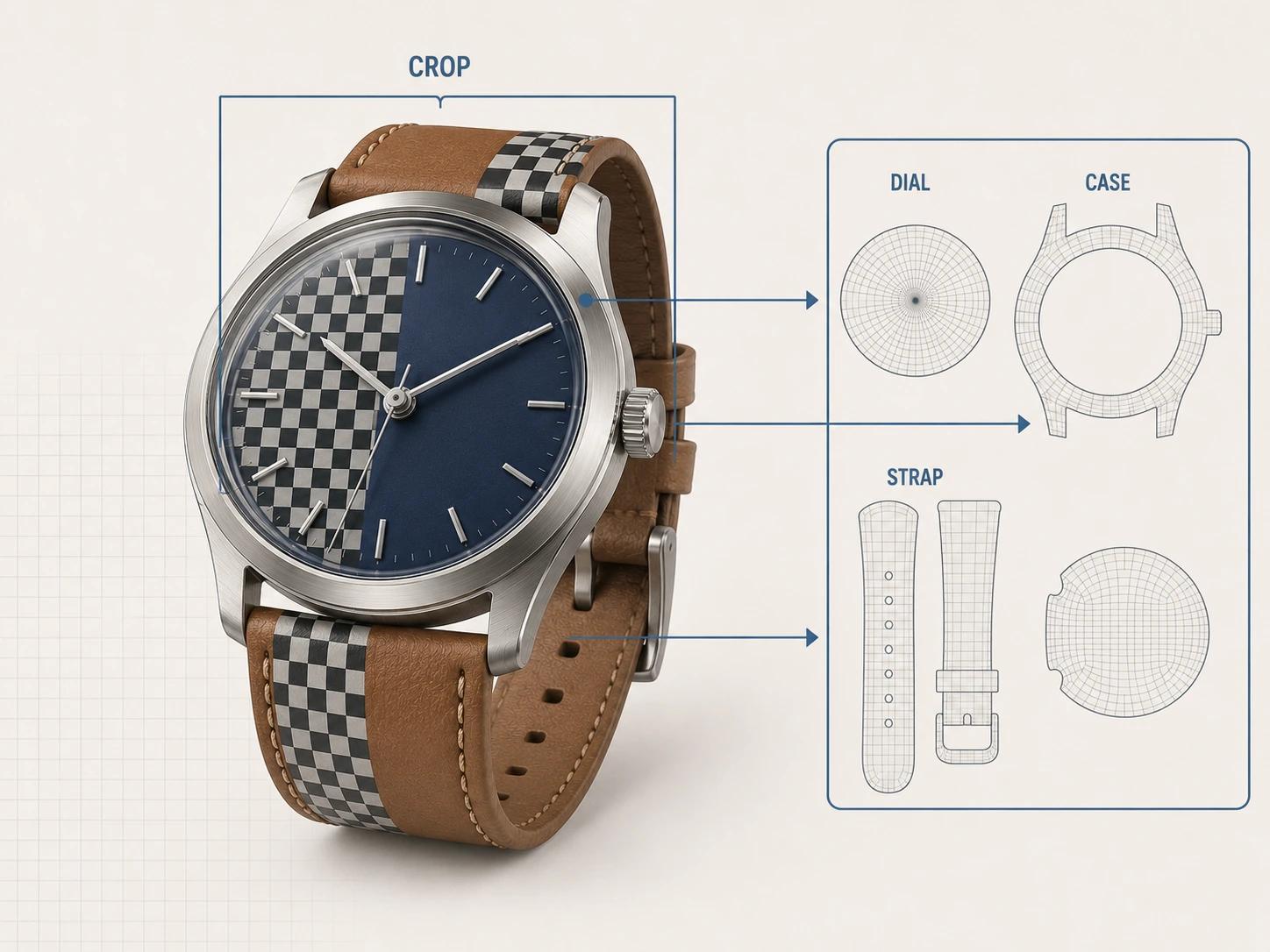
Record the chosen texture-set structure and target destination beside the ledger. Do not invent a universal texels-per-unit value or map resolution. Approve allocation by checking the actual crop at delivery size, then test any reduced derivative separately.
Build materials from response, scale and direction
A material name is not a material specification. OpenPBR's versioned parameter reference separates base color, metalness, diffuse and specular roughness, anisotropy, index of refraction, transmission, coat, normals and tangents, among other controls.[7] The exact implementation varies by renderer, but the separation is useful: it forces the team to describe what the surface does rather than call it "premium steel" or "tan leather."
Build one evidence sheet per visible zone:
- The brushed steel case needs the approved alloy or finish reference, brush direction, roughness range, transition at machined edges and only the variation the product state justifies.
- The domed glass needs thickness, surface shape, transmission and reflection behavior that remain coherent at the rim. A dark outline painted into a texture is not a glass construction.
- The navy dial needs its own substrate and finish description. Color, clear coat, metallic response and radial or matte structure should not be collapsed into one blue swatch.
- The tan leather strap needs grain at credible scale, direction along the strap, a distinct cut edge, stitching relief and any finish layer visible in the reference.
- Polished hands and markers need reflected shapes and clean edges. Flat gray is not evidence of metal.
Approve a clean material before adding dust, fingerprints, pores or wear. Imperfection must have a cause, scale and product state. The same noise map across glass, steel, dial and leather is not realism; it is one effect ignoring four surfaces.
For downstream glTF work, translation is explicit. The glTF 2.0 specification treats base color separately from a linear metallic-roughness texture, assigns roughness to the green channel and metalness to blue, and defines tangent-space normal textures plus normal, tangent and texture-coordinate attributes.[8] A renderer-native material may therefore need baking or remapping. Check the exported file rather than assuming a familiar material name carries its full response.
Review closeups with a controlled ladder
The closest intended view is the acceptance condition, not a surprise requested at the end. Use this original Double Edged diagnostic ladder while keeping the camera and crop comparable:
- Clay silhouette views expose proportion, construction and gaps.
- A glancing highlight exposes edge widths, surface waviness and pinching.
- A normal visualization exposes unexpected splits, locked data and tangent discontinuity.
- A high-contrast UV checker exposes stretch, density jumps, seams and orientation.
- Neutral material-response views isolate steel, glass, dial and leather behavior without campaign grading.
- The intended macro crop tests the approved output size and depth of visible detail.
- Variant toggles and a representative export test naming, material mapping and downstream parity.
Log each finding by part, view, gate and controlling reference. "Case looks fake" is not actionable. "A broad highlight bends across the upper-right lug although the controlling top view shows a plane" points to geometry, topology or normals. Change one cause at a time and rerun the affected rung.
Approval applies to a named revision and view envelope. A new underside animation, an exploded view or a tighter crop can expose previously out-of-scope construction. Reopen only the gates that the new use changes, then issue a new derivative revision.
Keep variants traceable before multiplying files
Separate material variants from geometry variants. A navy dial versus a silver dial may share geometry if markers, print and construction truly match. A different crown, hand set, lug shape or strap hardware is a geometry change even when a material toggle can make a preview look close.
Keep stable product, part, material-zone and variant IDs in the master. Record which meshes and materials each sellable state uses. The ratified Khronos KHR_materials_variants extension can represent finite, premade material variants compactly for runtime switching, but its own design notes say complex configurator authoring is outside its goal.[9] Use it when the destination supports the extension and the product states fit that bounded model. Keep pricing, availability and multidimensional business rules in the application system that owns them.
Do not duplicate a whole scene for every strap color unless the production need justifies it. Shared geometry and named material assignments reduce drift. When geometry differs, preserve the difference honestly and test every affected closeup.
Preserve animation and real-time options without bloating the master
Plan articulation while parts are still separable. For a wristwatch, the hour, minute and second hands need usable pivots and hierarchy. The crown may rotate or pull. A strap may need bend-friendly topology, while the rigid case should not inherit unnecessary deformation density. Naming and neutral transforms make these decisions easier to hand off.
Keep one editable visualization master, then derive files for their destinations. A real-time derivative may need deliberate triangulation, baked detail, simpler material layers, compressed textures or reduced hidden geometry. None of those choices defines a universal polygon or texture budget. The target viewer, device class, interaction, closest camera and measured performance budget control acceptance.
The glTF specification's explicit normals, tangents, UVs, nodes, materials and animation structures show why export is a translation step rather than a Save As operation.[8] Test a representative derivative for silhouette, normal-map orientation, material response, hierarchy, pivots, animation and variant switching. Keep that result separate from approval of the high-fidelity master.
The guide to CAD, DCC and real-time model differences owns the broader representation comparison. When commissioning this work, the custom 3D modeling services RFP guide owns rights, review rounds, deliverable wording and handoff terms. This article supplies the craft tests those documents can reference without turning into a generic procurement template.
Use this photorealistic modeling quality checklist
- [ ] The approved product revision, dimensions, views and closest crop are named.
- [ ] Silhouette, visible thickness, part splits, seams, gaps and intersections match controlling evidence.
- [ ] Edge widths and profiles are product-specific; no global bevel preset stands in for reference data.
- [ ] Normals produce intentional hard and soft transitions without hiding a wrong shape.
- [ ] Topology supports the required subdivision, reflection flow, deformation, editing and export behavior.
- [ ] UVs pass checker tests for stretch, seam visibility, density and directional material alignment.
- [ ] Texel allocation is recorded by surface, crop, visible detail, variant reuse and destination.
- [ ] Materials are approved through response, scale and direction, not color names or random imperfection.
- [ ] The fixed closeup ladder has been run on a named revision.
- [ ] Material and geometry variants map to stable product and part identifiers.
- [ ] Animation pivots, hierarchy and deforming parts are prepared only where planned.
- [ ] Every real-time or motion file is a traceable derivative with its own acceptance result.
- [ ] No universal tolerance, polygon count, texture size or platform guarantee has been invented.
Bring the model and its evidence into production
The 3D product modeling service is the commercial path when a product needs a high-fidelity visualization master, controlled variants or planned derivatives. Bring one representative product, the closest intended crop, controlling references, variant list and downstream uses. Those inputs make geometry, UV and material decisions reviewable before the catalog multiplies them.