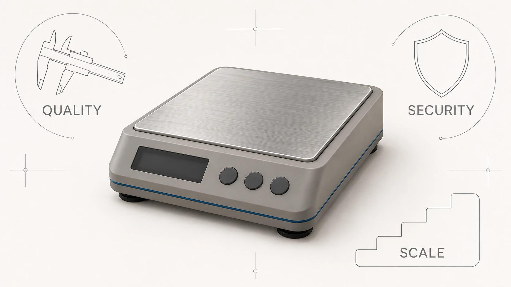
Photorealistic 3D product rendering is not the result of one perfect shader, a higher sample count or a final contrast pass. It is the agreement of six decisions: geometry, materials, lighting, camera, color management and art direction. When those decisions describe the same physical object under the same visual logic, the image feels coherent. When one contradicts the others, polish tends to make the contradiction clearer.
This guide tests those six variables on one brand-neutral countertop espresso machine: a compact rectangular body in brushed stainless steel, matte graphite side panels, a black drip tray, a cylindrical steam wand and a walnut control knob. The object is specific enough to expose weak edges, implausible finishes and distorted proportions without pretending to be a completed client project.
If you need the wider production sequence, source-input requirements or delivery package, start with 3D Product Rendering: Process, Inputs and Deliverables. This article stays at the craft boundary: what makes a single product image believable and how to diagnose why it is not.
Realism is consistency, not polish
*Physically Based Rendering* describes photorealistic rendering as creating an image of a 3D scene that is indistinguishable from a photograph of the same scene, then immediately qualifies “indistinguishable” as an imprecise judgment involving a human observer.[1] That qualification matters. A render can be physically computed yet visually unconvincing, or carefully art-directed yet still expose a false product fact.
The same source separates the simulation into components including the camera, object geometry, light sources and scattering at surfaces.[1] There is no single realism dial. The renderer only resolves the scene it has been given. More computation can reduce noise; it cannot decide whether the housing radius, brushed direction, camera distance or display transform represents the intended product.
For product work, a useful definition is narrower: realism is the absence of unexplained contradictions at the intended viewing size. The silhouette should agree with the construction. Highlights should agree with both surface finish and light shape. Perspective should agree with a plausible camera position. Color should survive the path from scene values to the approved output. Art direction should make those facts legible without rewriting them.
The six-variable realism teardown
The table below is an original diagnostic framework for this guide, not a formal rendering standard. Each row asks what must be true on the same espresso machine and what a reviewer can actually inspect.
| Variable | Evidence on the espresso machine | Common realism break | Approval question |
|---|---|---|---|
| Geometry | Correct silhouette, edge radii, wall thickness, seams, gaps and part relationships | Razor edges, melted transitions, floating parts or detail that changes scale | Do the form and construction match the approved product from every required view? |
| Materials | Distinct brushed steel, coated polymer, rubber, chrome and walnut responses | Materials separated only by color, uniform roughness or texture at the wrong scale | Does each zone react to the same light like the intended substrate and finish? |
| Lighting | Broad reflections that describe metal, readable shadow structure and credible contact | Brightness without shape, arbitrary rim lights or reflections with no plausible source | Can a reviewer infer the product’s form and finish from the highlight and shadow pattern? |
| Camera | Intentional distance, field of view, height, tilt, crop and focus | Bulging front features, compressed depth or a “miniature” depth-of-field effect | Do proportions remain credible while the chosen features receive emphasis? |
| Color management | Correct input interpretation, scene-linear calculations and a named output transform | Washed roughness, shifted finish color, clipped highlights or inconsistent review exports | Is everyone approving the same transform and delivery condition? |
| Art direction | One clear hero feature, controlled asymmetry, believable wear level and useful negative space | Perfect-but-sterile surfaces, decorative clutter or drama that conceals product truth | Does the image feel intentional without inventing or hiding a product fact? |

No row compensates cleanly for another. Strong lighting can reveal bad geometry but cannot fix it. A well-matched steel shader cannot create a reflection if the scene gives it nothing useful to reflect. A tasteful grade cannot recover highlight information that was clipped or a normal map that was interpreted as display color.
A controlled teardown method
Change one variable at a time. Keep a fixed camera and neutral review light while approving geometry. Keep approved geometry, camera and review light while resolving materials. Only then move into the hero lighting and composition. This order is a diagnostic recommendation, not a claim that every production contract needs six separate stages.
For the espresso machine, save six comparable checkpoints:
- Neutral form: one gray material, diagnostic three-quarter and side views, no depth of field.
- Material response: approved zones under a broad neutral source, with close crops for steel, graphite, rubber and walnut.
- Light structure: the same camera with final-sized emitters, reflection cards or environment and a grounded contact shadow.
- Camera choice: two or three deliberate distance-and-field-of-view combinations at the same output crop.
- Color pipeline: a scene-linear master viewed through the agreed output transform, plus a delivery export opened in the receiving workflow.
- Art-directed final: the selected hierarchy, background, controlled imperfection and final crop.
A checkpoint should answer a named question. “Version 12 looks better” is weak evidence. “The wider top-front radius now carries a continuous highlight that agrees with the drawing and side reference” makes the decision traceable.
1. Geometry: give light a credible object
Product geometry is judged first by silhouette and part relationships, then by how surfaces turn through light. The Blender 5.2 manual makes the basic edge point directly: real objects are not infinitely sharp, so beveling corners and edges improves realism.[2] That is not permission to add one global bevel. A stamped steel housing, molded polymer panel, machined knob and rubber foot have different radii and transition logic.
On the espresso machine, inspect the top-front corner, tray opening, panel seams and steam-wand joints. A zero-radius housing produces a mathematically thin highlight that disappears or flickers with small light changes. An oversized radius makes sheet metal look inflated. A seam with no depth reads like a texture line; a gap that is too wide makes the assembly look loose. Use drawings, CAD sections, measured references or a physical sample to decide, and label any visual interpretation that remains.
Normals matter because they control how shading interpolates across the mesh, but smooth shading should not disguise the silhouette. Review a clay render, a specular diagnostic and the final crop. If the edge only works through a shading trick from one camera, it is not a dependable product edge. Model visible thickness where the camera can see into the tray, vents or panel joins; do not let single surfaces expose impossible construction.
2. Materials: reproduce response, not a material name
“Metal,” “black plastic” and “wood” are categories, not material specifications. The versioned OpenPBR surface reference separates base color and metalness from diffuse roughness, specular roughness, anisotropy, index of refraction, transmission, coat and geometry normals or tangents.[3] That structure is useful even outside an OpenPBR implementation: it shows why matching a swatch color alone cannot define a finish.
Microscopic roughness changes the angular distribution of reflected and transmitted light. Microfacet theory models that small-scale variation statistically; the facets may be too small for the camera to resolve, yet they strongly affect scattered-light direction.[4] In practical review terms, roughness changes the width and clarity of a highlight. Directional microstructure changes its orientation. A brushed steel front should not respond like isotropic chrome, and a matte graphite coating should not become dead gray simply because its highlight is broad.
Build a material evidence sheet for each visible zone:
- Brushed steel: base metal response, brush direction, highlight spread, subtle directional variation and the scale of fine structure.
- Matte graphite coating: substrate or coating assumption, broad specular response, fine relief and any approved variation.
- Black rubber: darker value without crushed detail, softer reflection and credible contact at the feet or tray.
- Walnut control knob: grain direction that follows the part, believable scale, edge finish and a coating layer if the reference shows one.
- Polished wand: controlled reflected shapes rather than a flat gray cylinder or a white stripe painted into the texture.
Avoid random “imperfection maps” as a shortcut. First establish the clean manufactured finish. Then add only evidence that belongs to this product state: faint handling, machining variation, dust or wear if the brief calls for it. Imperfection should have cause, scale and placement. Uniform noise across steel, rubber and wood is one procedural effect pretending to be three materials.
3. Lighting: reveal the evidence
Lighting does not merely make the object visible; it supplies the shapes that reflective materials return to the camera. Official light documentation distinguishes a surface-like area emitter from a point source and notes that area lights produce shadows with soft borders based on the emitter’s size.[5] The same documentation advises using realistic light size and color when realistic results are the goal.[5]
For the espresso machine, start with one broad key source that travels across the steel body and rounded front edge. Add only what the product needs: a controlled fill to keep the graphite panel readable, a narrow card or source to describe the steam wand, and a ground relationship strong enough to establish weight. Watch the reflections, not only the light objects. A polished cylinder can turn black if it reflects an empty black region even when the scene is technically bright.
Use neutral review lighting before the campaign look. If a material only reads correctly under one dramatic rim, its definition is probably fragile. Conversely, a flat light tent can erase the contrast that reveals curvature. The goal is not shadowlessness; it is a hierarchy in which broad and narrow transitions explain form.

4. Camera: control proportion before composition
A perspective camera makes distant objects appear smaller and causes receding parallel lines to converge. Its focal length controls field of view: longer focal lengths show less of the scene, while shorter focal lengths show more.[6] In a fixed camera position, that changes framing. When the camera is moved to preserve the same framing, the changed distance also changes the apparent relationship between near and far parts. That is why “use a longer lens” is incomplete direction.
Test the machine at the final aspect ratio. A close, wide view may enlarge the group head and shrink the rear housing. A distant, narrow view can make the product feel flatter. Neither is automatically wrong; the question is whether the chosen perspective communicates the approved proportions and intended feature hierarchy.
Set camera height and tilt from the buying question. Show enough top surface to explain controls, but do not reveal so much that the machine appears short. Use lens shift or a corrected composition when verticals must remain controlled rather than rotating the camera without noticing the convergence change.[6] Add depth of field only when it supports scale and attention. Product-critical details should not become collateral blur.
5. Color management: preserve the image from scene to delivery
A renderer can calculate plausible light and still deliver the wrong-looking finish if inputs and outputs are interpreted inconsistently. Current Blender documentation states that rendering and compositing are best performed in a scene-linear color space and that correct assignments allow conversion to and from that space.[7] It also distinguishes normal and displacement maps as non-color data.[7] Applying a display-oriented color transform to a normal map changes values that were meant to drive direction or height, not appearance.
Separate three decisions:
- Input interpretation: identify which textures contain color and which contain data. Record the intended source space for measured or painted color textures.
- Scene processing: keep lighting and compositing in the agreed scene-linear working space, with exposure set deliberately rather than used to rescue one material.
- Output viewing: choose a view or output transform for the target and keep it stable through review and export.
ACES documentation illustrates the final distinction clearly: an Output Transform turns scene-referred image data into a rendered state for a specific output device and viewing condition, combining a rendering transform with display encoding.[8] ACES is not mandatory for every still, but the separation is. Scene-linear values are not a finished product image, and an attractive viewport is not proof that the receiving file will match.
For the espresso machine, retain highlight separation in the steel, visible structure in the graphite and plausible warmth in the walnut without forcing all three through a late saturation or contrast move. Review the delivery export in the workflow that will actually use it. If two reviewers see different transforms, their material notes are not directly comparable.
6. Art direction: make the truth legible
Art direction decides what the accurate scene should say first. For this machine, the hero might be the stainless housing and control layout, the material contrast around the walnut knob, or the clearance around the steam wand. Pick one. Lighting, camera, crop and background should reinforce that hierarchy rather than compete for attention.
Controlled imperfection is part of this decision, but perfection is not the same as cleanliness. A launch render may reasonably show a clean product. It still needs enough surface variation, contact and reflected environment to avoid looking detached. Add asymmetry where the physical setup would create it: one stronger reflected panel, a slight background falloff or a contact shadow that responds to the feet. Do not add scratches to signal “real” when the product is supposed to be new.
Art direction must not conceal unresolved accuracy. A black edge that hides a wrong seam, a blown highlight over uncertain artwork or depth of field across an unapproved component is not a craft solution. Keep diagnostic views alongside the hero so product truth remains reviewable.

Diagnose failure signatures in the right order
The visible symptom is not always the root cause. Use this compact troubleshooting table before adding polish.
| Symptom | Check first | Then check | Avoid as the first response |
|---|---|---|---|
| Steel looks like gray plastic | Metal/dielectric assignment and roughness | Reflected environment, brush direction and color pipeline | Raising contrast across the whole image |
| Product looks toy-sized | Camera distance, field of view and camera height | Edge radii, texture scale and depth of field | Adding random scratches |
| Form feels flat | Silhouette and surface curvature | Source size, placement and reflection shapes | Increasing saturation |
| Edges look computer-sharp | Product-specific radii and visible thickness | Normals, tessellation and highlight placement | Bloom or sharpening |
| Black finish has no detail | Roughness response and exposure | Fill shape, output transform and display condition | Making the base color mid-gray |
| Render feels sterile | Contact, variation with physical cause and visual hierarchy | Background relationship and crop | Applying the same noise map everywhere |
| Final differs from review | Input tags, working space and output transform | Export profile, file interpretation and receiving app | Retuning materials in the delivery file |
This order protects cause and effect. Fix geometry before a grade, material response before decorative texture and color interpretation before arguing over a swatch. Freeze approved variables while testing the next one so a better image does not quietly introduce a less accurate product.
Approve realism at the intended size
A close diagnostic render can reveal a bad seam or texture scale, but the final image must also work where it will be used. Review the hero crop, a representative smaller crop and any detail view included in scope. At each size, ask six observable questions:
- Does the silhouette and construction still read correctly?
- Do materials remain distinct through their response, not just their color?
- Do highlights and shadows explain the form without hiding important features?
- Does perspective support rather than distort the product hierarchy?
- Are input, working and output color decisions recorded and repeatable?
- Does the art direction add emphasis without changing product truth?
Record failures by variable. “The graphite panel loses separation at the delivery crop” is more useful than “not realistic enough.” It names the location and allows a targeted check of material, light and output transform without reopening the approved camera or geometry by default.
Keep the craft-guide boundary clear
This teardown does not choose software, compare studios, set project fees or prescribe a universal production schedule. Those decisions depend on a wider brief. The related 3D product rendering cost guide owns cost drivers and example scopes; this page owns the craft diagnosis.
Use the six variables to prepare a review: one product, one approved revision, one intended crop and one named question for each checkpoint. That gives a production team something more precise than “make it photoreal” without pretending that realism can be reduced to a preset.