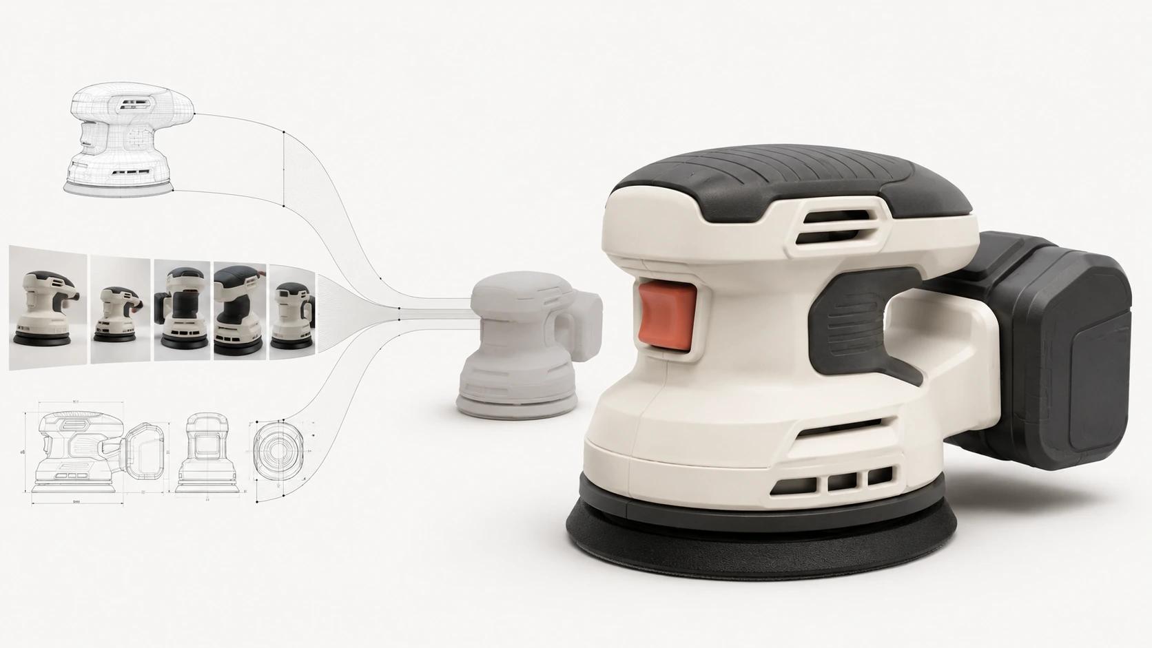
A studio does not simply convert CAD, photographs or drawings into a finished product image. It first decides what each input can prove, what remains unknown and which person can approve an interpretation. Only then does it translate or reconstruct the geometry, build the visible materials, compose the shot and render the final pixels.
The three starting paths are different. CAD usually supplies the strongest dimensional and assembly evidence, but it may be built for manufacturing rather than presentation. Photos show the physical object's current appearance, yet perspective, lighting and unseen surfaces limit what can be inferred. Drawings can control profiles and dimensions, but a 3D object still has to be constructed between the documented views.
A reliable project therefore separates source evidence, reconstruction work, assumptions and approvals. This guide follows those four ideas through a complete three-path input-to-render workflow. It is not a vendor scorecard or a universal claim about how every studio works.
CAD, photos and drawings answer different questions
The best input is not the file type with the most technical-sounding name. It is the current source that controls the product fact being reviewed. One project may use CAD for form, photographs for finish and a dated drawing for revised label placement.
| Starting path | Strongest evidence | Typical gaps | Reconstruction work | First useful approval |
|---|---|---|---|---|
| CAD | Units, primary surfaces, part relationships and engineered features | Wrong revision, suppressed parts, render-unfriendly topology, presentation detail and material appearance | Import or translate, tessellate, clean normals and seams, organize visible parts, add approved commerce detail | Neutral views confirming silhouette, scale, assembly and visible features |
| Photos | Current visible condition, finish character, graphics, wear, seams and small details | Exact scale, lens effects, hidden faces, internal construction and symmetric features outside the frame | Solve or approximate cameras, model manually or reconstruct from overlapping images, clean geometry and fill documented gaps | Multi-angle neutral model checked against known measurements and the photo set |
| Drawings | Orthogonal profiles, stated dimensions, radii, hole locations, sections and callouts | Undocumented transitions, hidden construction, ambiguous projection, obsolete notes and finish behavior | Trace controlling profiles, construct volumes, apply dimensions and rebuild missing transitions explicitly | Comparison views and dimension checks against each controlling sheet |
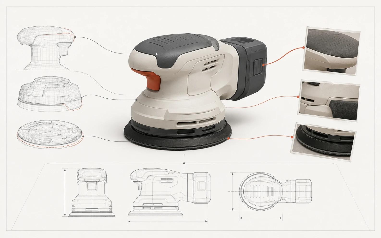
These are starting conditions, not mutually exclusive methods. A photo does not override a released dimension merely because it looks newer. A CAD file does not prove a finish. A drawing marked superseded should not control a launch product. The studio needs an evidence hierarchy before it needs a beautiful shader.
First establish product truth
Create a source index before opening the modeling scene. For every file or physical reference, record the product or SKU, revision, date, units, owner, intended authority and readiness state. A short label works:
- Controlling: approved to decide a named product fact.
- Supporting: useful for interpretation but not allowed to override a controlling source.
- Conditional: usable only with a written assumption.
- Superseded: retained for history, not production.
- Blocked: unreadable, unlicensed or too uncertain for the affected decision.
Then write a source hierarchy. For example, released CAD controls overall form; drawing B-17 controls a revised port location; the approved physical sample controls the coating texture; vector artwork controls the label; brand direction controls the image mood. When sources conflict, log both versions and ask the named product owner to choose. Blending them into a plausible compromise creates a product revision that may never have existed.
Also lock the intended views. A rear detail, transparent cutaway or exploded shot exposes geometry that a frontal hero never shows. The required cameras determine which hidden surfaces must be reconstructed now. The broader 3D product rendering process, inputs and deliverables guide covers complete scoping and handoff; this guide stays focused on how the three source paths become trustworthy geometry.
Path 1: translate CAD into render-ready geometry
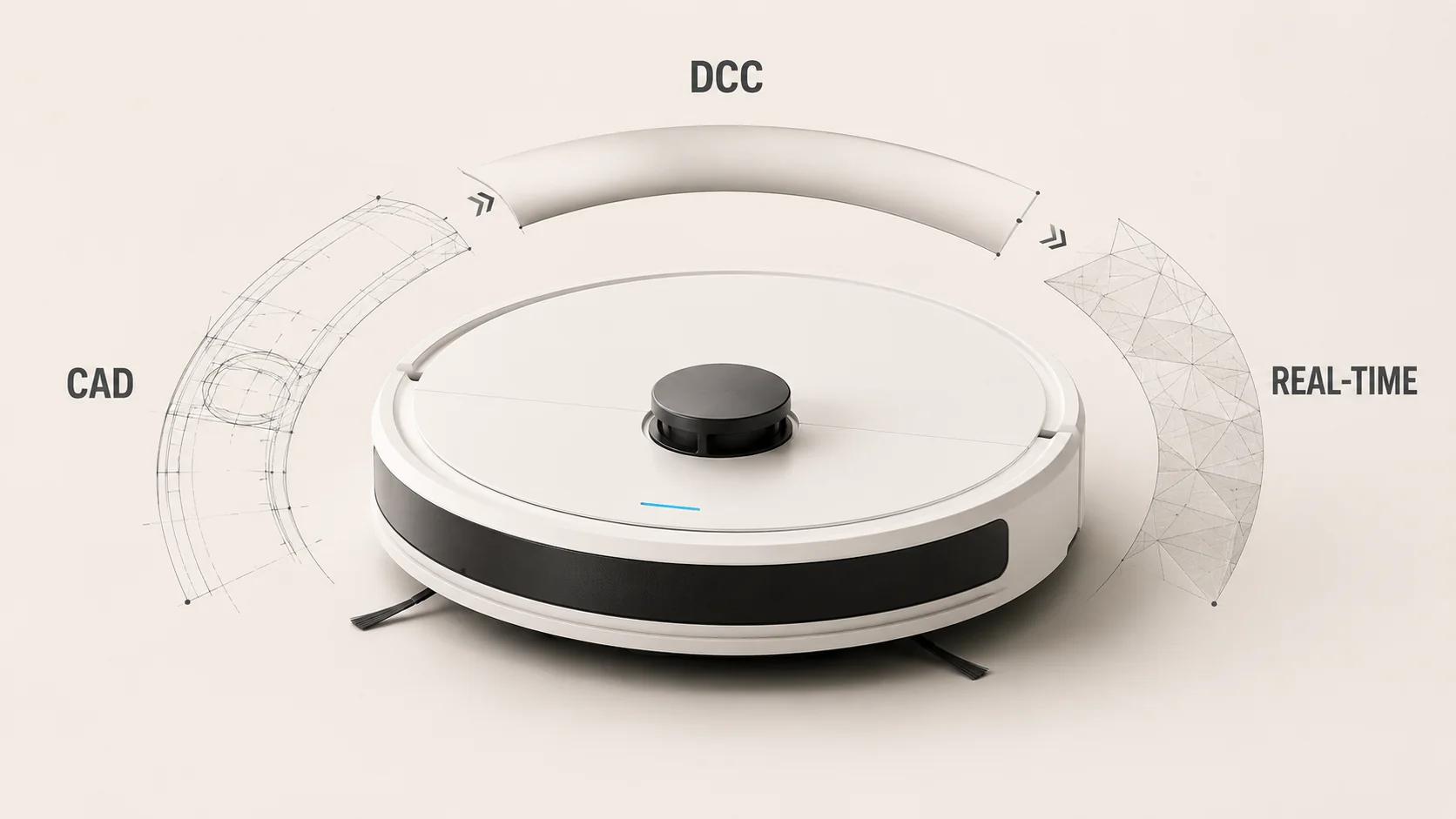
CAD is often the shortest path to approved form, not a finished render asset. Translation still involves choices. Autodesk's current DWG/DXF file-link documentation exposes controls for welding, smoothing, normal orientation, texture coordinates and surface deviation. It states that a smaller maximum surface deviation produces a more accurate mesh with more faces, while a larger value produces fewer faces and less surface accuracy.[1]
A practical CAD path has five moves:
- Confirm identity and units. Match the file to the product revision, assembly state and declared unit system. Keep the source untouched and work in a versioned production copy.
- Inspect the assembly before simplifying. Identify duplicate bodies, suppressed components, construction geometry, hidden fasteners and parts that will become material zones or moving elements.
- Choose the translation deliberately. Set tessellation or conversion quality for the closest required camera, not for an arbitrary polygon target. Check curved silhouettes, holes, thin gaps and face normals after import.
- Prepare visible geometry. Repair shading, remove irrelevant internals only when the shot plan permits it, separate meaningful material zones and add presentation details that the CAD never represented, such as a controlled seam or approved label thickness.
- Approve a neutral model. Render simple diagnostic views without persuasive materials. Compare critical dimensions, silhouette, gaps and part positions with the controlling evidence.
The assumption log may still be substantial. CAD might omit a cable path, flexible seal, textile element or late prototype change. It may contain manufacturing tolerances that should not be exaggerated visually. Each interpretation should name the affected feature, the source used and the approver. “Imported successfully” is a software event; it is not product approval.
Path 2: reconstruct the product from photos
A photo-led project can mean manual reference modeling, photogrammetry or a combination. Do not promise an automatic scan merely because many images exist. First determine whether the photographs were captured as evidence or only as attractive product shots.
Perspective images do not preserve every dimension directly. Blender's camera documentation explains that perspective makes distant objects appear smaller and parallel lines converge; focal length and sensor settings change the field of view.[4] The studio can match a camera and compare a model against a photograph, but a single view still leaves depth and unseen surfaces unresolved.
For image-based reconstruction, coverage matters. RealityScan advises moving around the object, completing loops, progressing from whole-object coverage to details and making each surface point visible in at least two high-quality images.[2] Its alignment documentation describes camera registration through common features and poses, and recommends more than 60 percent overlap between neighboring images for best quality in that specific workflow.[3] That is useful capture guidance, not a guaranteed accuracy claim.
Ask for a measured scale reference, several heights, sharp uncropped originals and close views of material transitions, seams, labels and underside features. Keep exposure and focus stable where possible. Highly reflective, transparent, featureless or changing surfaces may need a different capture treatment or manual rebuilding. If dimensional accuracy matters, use controlling measurements rather than treating visual alignment as metrology; RealityScan itself cautions that guaranteed precision warrants professional support.[2]
The reconstruction sequence is: organize and assess the set; identify usable camera groups; establish scale from a trusted measurement; create a coarse volume; align it across views; add visible features; and record unseen geometry as an assumption. Photogrammetry output, when used, may still need cleanup, retopology, hole filling and deliberate rebuilding before it supports smooth product imagery.
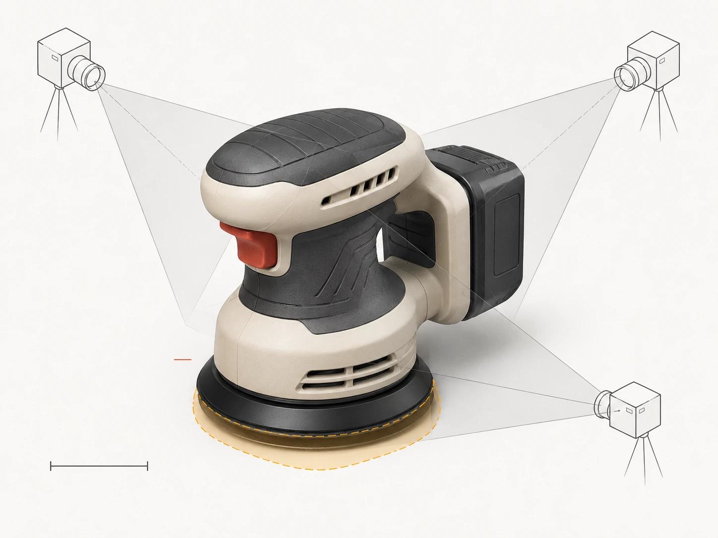
Approve the photo path in neutral material from multiple angles, including views that were not in the marketing set. A model that matches one photograph can still be wrong in depth. The review should distinguish “visually consistent with supplied photos” from “dimensionally verified against approved measurements.”
Path 3: construct the product from drawings
A drawing-led build begins with projection, scale and authority. Blender distinguishes perspective projection, where parallel lines converge, from orthographic projection, where they remain parallel.[4] Autodesk's Fusion documentation places measurement annotations on orthogonal drawing views and supports linear, angular, radius, diameter and other dimension types.[5] That is why a dimensioned front, side and top set is more useful for reconstruction than one perspective sketch.
Import each controlling view on a known plane, calibrate it from a stated dimension and align shared datums. Build the primary volumes and profiles first. Add holes, radii, draft, wall thickness and repeated features from their callouts. Use section or detail views to resolve transitions that the exterior outlines cannot show.
Do not infer symmetry, constant thickness or a smooth blend unless the sheets establish it or an approver accepts it. Hand sketches and concept drawings can still start a model, but their uncertain scale and missing construction should be visible in the assumption register. The first review should show the rebuilt model beside the controlling projections and list every unresolved rear, underside or internal feature.
The three-path input-to-render workflow
The following is an original Double Edged editorial framework, not a formal industry standard. It keeps the path-specific work visible until all three routes reach the same approval gates.
| Stage | CAD path | Photo path | Drawing path | Approval output |
|---|---|---|---|---|
| 1. Lock evidence | File, revision, units and assembly | Image set, capture conditions and measurements | Sheet set, revision, projection and scale | Source index and hierarchy |
| 2. Normalize | Translate and inspect bodies | Group cameras and set trusted scale | Align views to datums and dimensions | Reconstruction plan with exclusions |
| 3. Build form | Tessellate, clean and organize | Block, align, scan or model, then clean | Construct profiles, volumes and transitions | Neutral model plus assumption register |
| 4. Resolve unknowns | Add omitted visible detail | Rebuild hidden or unreliable regions | Interpret undocumented surfaces and assembly | Product-owner decisions recorded by feature |
| 5. Lock geometry | Check dimensions, silhouette and parts | Check all views and measured controls | Check projections, dimensions and sections | Dated geometry approval |
| 6. Create the render | Add approved materials, cameras, lighting and final output settings | Add approved materials, cameras, lighting and final output settings | Add approved materials, cameras, lighting and final output settings | Material review, look approval and accepted final |
Once geometry is locked, source paths converge. Material creation should still be evidence-led. Blender's current Principled BSDF documentation separates base color, roughness, metallic response, index of refraction, transmission, coat, normals and sheen.[6] A color value alone therefore does not describe how a coated metal, clear polymer or woven surface responds to light. Supply finish samples, controlled photographs, supplier data or approved comparisons, then review materials under a neutral light before campaign lighting changes their appearance.
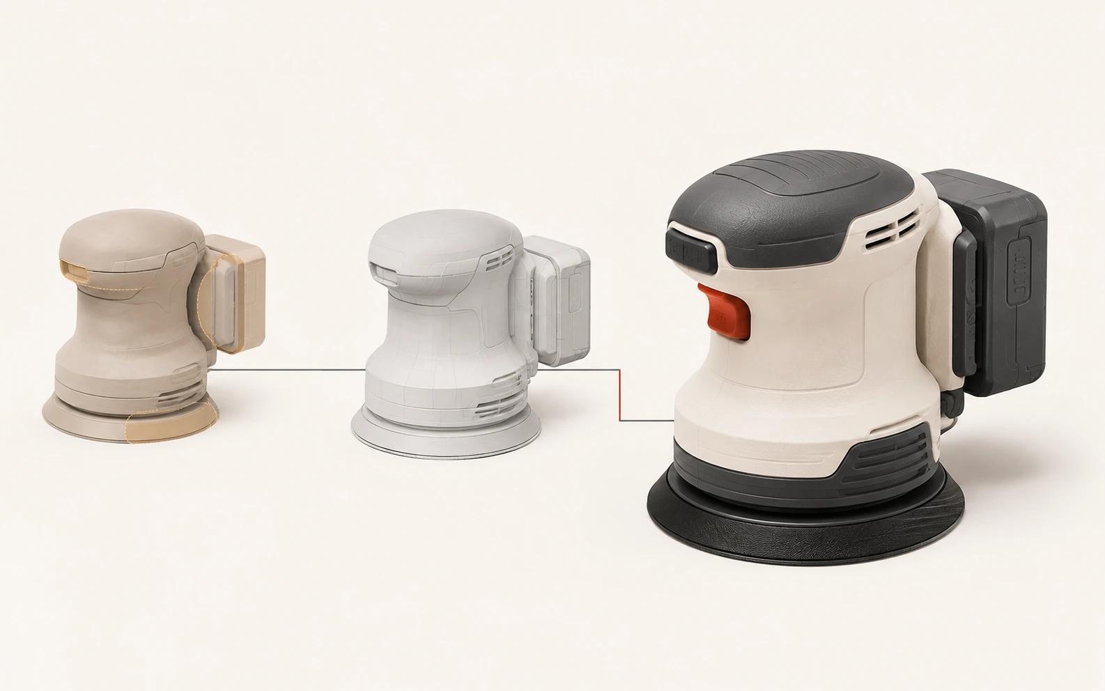
Final shot production follows geometry and material approval: build the camera and composition, establish lighting and background, render a representative view, correct agreed issues, check the full shot or variant set and export to the specified dimensions and color workflow. That shared end stage should not erase the provenance record that explains how the model was built.
Turn every assumption into an approval item
An assumption is not automatically a defect. It is a controlled decision made because the available evidence does not close a question. The defect is leaving it invisible until final review.
For each assumption, record the affected feature, temporary interpretation, why the evidence is insufficient, views or variants affected, decision owner, required evidence and deadline. Attach a marked neutral render rather than a paragraph alone. Close the item as verified, approved interpretation, revised or excluded from scope.
Those statuses matter. “Verified” means a controlling source established the product fact. “Approved interpretation” means the buyer accepted a bounded visual decision without claiming it is measured truth. Preserve that distinction in the model notes so a later SKU or camera does not inherit an interpretation as fact.
Combine paths when the evidence demands it
Most useful input packs are hybrids. CAD plus current photos can pair reliable form with real finish and assembly detail. Drawings plus photos can rebuild a discontinued or pre-production item when no usable 3D file exists. CAD plus a revision drawing can isolate a late design change without discarding the rest of the assembly.
Choose one controlling source per fact, not one controlling format for the whole product. A furniture team may use dimensions and construction drawings for scale, close photographs for grain direction and swatches for finish; the furniture product rendering guide follows that category-specific asset and shot plan. When the final images must meet consistent marketplace crops, backgrounds, naming and variant rules, continue with the marketplace-ready rendering checklist.
A useful first handoff contains the current product ID and revision, the source index, controlling dimensions, all available input paths, material and artwork evidence, required views, named product and creative approvers, and an explicit list of known gaps. That is enough for a studio to propose the reconstruction route without pretending uncertain inputs are complete.