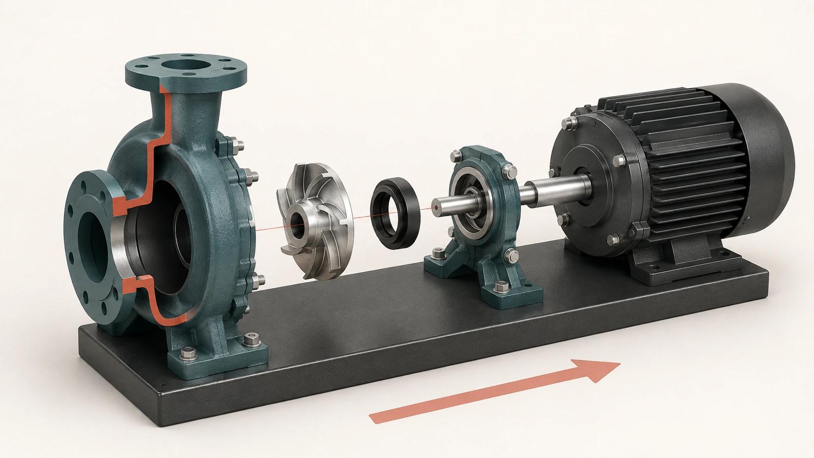
An exploded view answers, “What belongs where?” A cutaway answers, “What sits or moves inside?” Ghosting keeps the enclosure as context. Sequencing explains what changes first, next and last. In a useful 3D technical animation, each device has a specific job. Combining all of them in every shot usually makes the mechanism harder to read.
The practical rule is to start with the viewer’s decision, not an effect. A buyer may need to understand why a compact pump is serviceable. A sales engineer may need to explain the path through its impeller and volute. A trained technician may need a visual companion to an approved procedure. Those are different deliverables, even when they use one 3D model.
This guide owns that technical planning problem. For the wider choice of animation formats and funnel uses, see 3D Product Animation: Formats and Use Cases Across the Funnel.
Choose the view by the question it must answer
The following selection matrix is an original Double Edged editorial framework. It is a briefing tool, not an engineering drawing standard or maintenance procedure.
| Viewer question | Best starting device | Useful when | Main planning risk |
|---|---|---|---|
| Which components belong to this assembly? | Exploded view | Part relationships, kits, modular construction and service access need to be visible at once | Spacing parts decoratively instead of preserving fit, axis and grouping logic |
| Where is the hidden component? | Ghosted enclosure | The outside shape must remain recognizable while one internal part is located | Too many transparent surfaces merge into unreadable layers |
| What is inside this region? | Cutaway or section | A cavity, channel, seal interface or clearance matters more than the full exterior | An unexplained cut plane can make the product look manufactured that way |
| What changes over time? | Sequence | Assembly states, operating states or approved task stages must be distinguished | Smooth motion can imply an order, access path or safety state that was never approved |
| Which item is being discussed? | Label, callout or trail line | A reviewer needs a stable name, number, direction or state | Labels drift, collide, become too small or claim authority they do not have |
The choice is not exclusive. A sequence can pause on an exploded state, then use a shallow cutaway for one internal relationship. The discipline is to nominate one primary question per shot and make every supporting device earn its place.
Use exploded views for relationships, not automatic instructions
Autodesk defines an exploded view as an assembly whose components have been moved from their assembled positions. Its Inventor documentation also notes that the view can use item numbers from a parts list or bill of material.[1] That makes the technique useful for a product overview, a spares discussion, a kit contents check or a serviceability story.
The spacing still needs mechanical logic. Keep concentric parts on a shared axis where that relationship matters. Move fasteners far enough to read, but keep them associated with the flange or cover they secure. Treat a motor, coupling and pump head as groups before separating smaller parts. Trails should describe the intended relationship rather than become decorative streaks.
Autodesk’s Fusion animation tutorial explicitly combines exploded views, trail lines and annotations to communicate an assembly design.[2] The production lesson is tool-neutral: displacement shows separation, trails show correspondence, and annotations identify the part or state. None of those devices proves a correct assembly order by itself.
A radial explosion can be attractive for a hero shot, yet a controlled axial explosion is often clearer when shafts, seals and impellers share a centerline. The brief should state which relationships must remain true, which components may be grouped, and whether the final frame is explanatory, bill-of-material aligned or merely promotional.
Use cutaways when internal position matters
A section view is defined by a cutting plane through a part or assembly and represents the surface area of that cut. Autodesk distinguishes this from a breakout, which removes a defined local area to expose an obscured part or feature.[4] In animation, the same distinction is useful even when the treatment is more pictorial than a formal drawing.
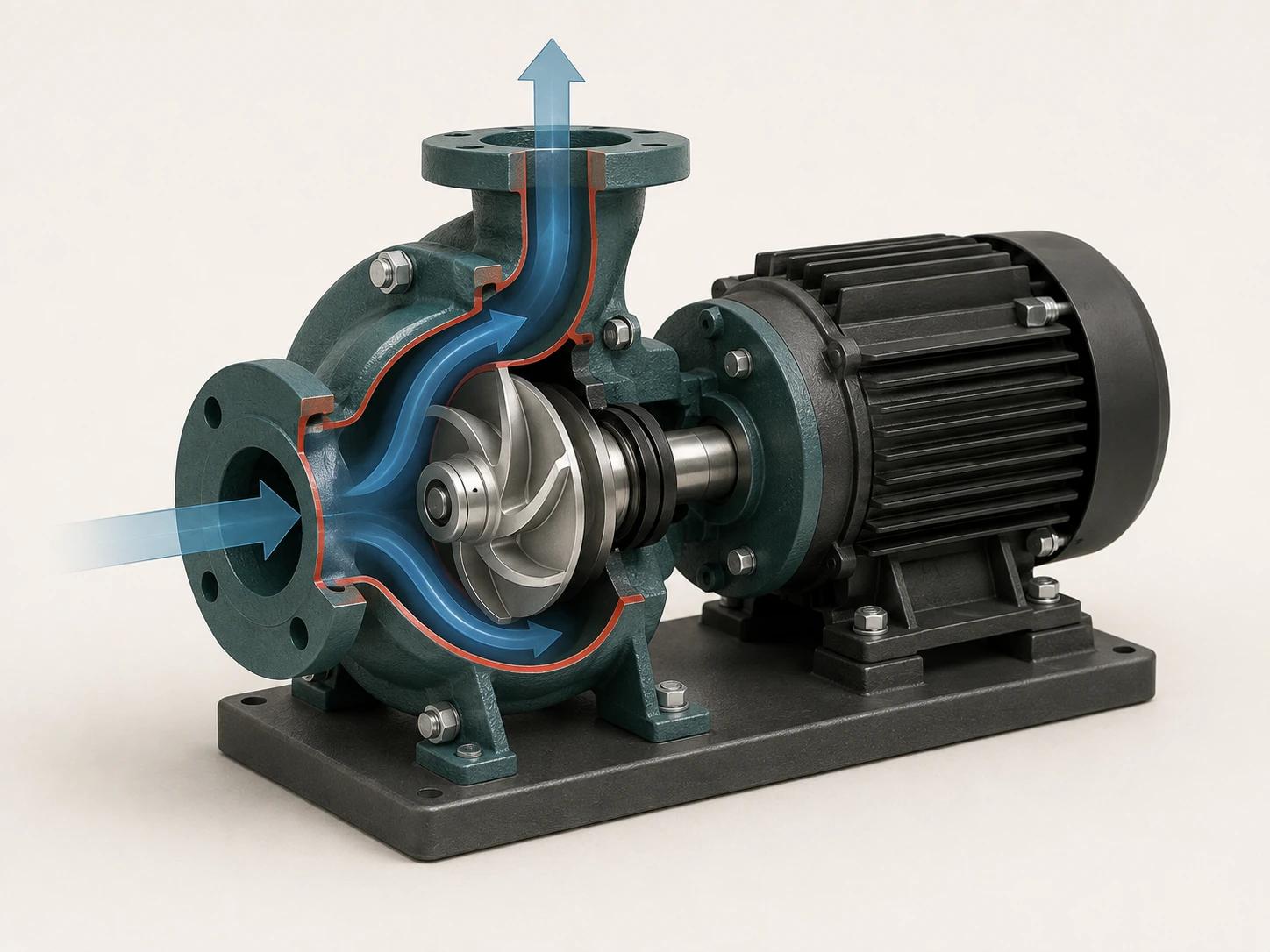
Use a full or half cutaway when the internal path is the subject: for example, the relationship among a pump inlet, impeller and volute. Use a local breakout when the viewer only needs to see the seal behind a cover. In both cases, show where material has been visually removed. A capped cut surface, restrained hatch, edge treatment or clearly introduced cutting plane prevents the cutaway from being mistaken for the product’s real exterior.
Do not let the cut destroy the context needed to interpret the mechanism. Keep enough casing, mounting geometry and connection points visible to orient the viewer. If the internal action crosses the cut plane, test the shot frame by frame; a part that looks clear while paused may appear to pass through solid material during motion.
ASME Y14.3 establishes requirements for orthographic and pictorial views on engineering drawing sheets and in models, and its public scope says view requirements are generally the same regardless of how those views are created.[5] A cinematic cutaway is not automatically a conforming engineering view. If it will function as controlled technical documentation, the responsible engineering team must identify the applicable drawing practice and review the actual deliverable.
Use ghosting to retain context
Ghosting lowers the opacity of an enclosure instead of removing it. It works when the viewer must locate an internal component relative to the complete product: a seal behind the volute, a shaft through a housing, or a cable route beneath a cover.
Opacity is not a substitute for composition. Two or three translucent shells can produce doubled edges and false depth cues. Start by ghosting one enclosing part, keep the target component opaque, and reduce irrelevant edges. If a cutaway answers the question more directly, use the cutaway.
State changes also need visual grammar. Fade the enclosure deliberately, hold long enough for the internal part to register, and restore it before moving to another question. A different material value or outline can separate “context geometry” from “active geometry” without turning the scene into a color legend.
Sequence one decision at a time
Technical motion needs authored states, not just a start frame and an end frame. Autodesk’s current Fusion tutorial demonstrates sequential component transforms, timed visibility fades, camera actions and reversal of a storyboard.[3] Those are production controls. Reversing animation playback does not establish that the real task is safe, feasible or approved in reverse.
For each step, record the incoming state, the single change, the outgoing state and the evidence that authorizes it. Then decide how long the viewer needs to inspect the result. A small seal may need a close camera and a longer hold; a cover moving away from the casing may only need enough time to preserve its axis.
Avoid simultaneous motion when order matters. If four fasteners leave at once, the shot communicates “these fasteners are associated with this cover,” not necessarily a real removal sequence. That may be fine for sales. It is not fine if the viewer could read it as a field instruction.
The medium choice belongs upstream. 3D Product Animation Video: Technical, Lifestyle or Hybrid? covers whether a technical sequence should stand alone or sit inside a broader story. Once the technical route is chosen, the shot plan below keeps one compact centrifugal pump coherent from frame to frame.
Plan the pump sequence before animation
This original planning table is intentionally product-specific. The example is a brand-neutral compact centrifugal water pump with a volute housing, impeller, seal, shaft and motor. It illustrates communication choices; it does not describe a particular manufacturer’s assembly or service procedure.
| Shot | Question | Product state and motion | Camera and visual device | Required approval evidence |
|---|---|---|---|---|
| 01 | What is the complete product? | Pump fully assembled and stationary on its base | Front three-quarter view; no transparency | Approved configuration and exterior model review |
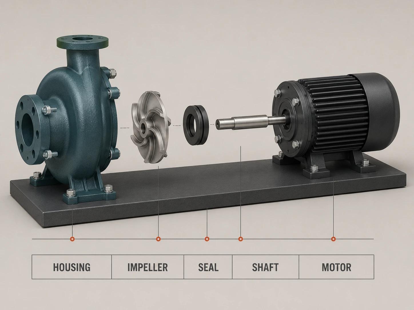
| 02 | Which major groups make up the pump? | Housing, impeller, seal, shaft and motor separate along a controlled axis | Locked camera; short trails; five stable labels | Approved component hierarchy and naming source |
| 03 | Where does the impeller sit? | Exploded parts return; housing becomes ghosted while impeller stays opaque | Slight camera move only after the state settles | Reviewed spatial relationship in the approved model |
| 04 | What internal region is being discussed? | A declared half cut reveals the impeller and volute cavity | Cut surface treatment; one restrained flow cue | Engineering review of the cut plane and explanatory path |
| 05 | What should the viewer remember? | Product returns to its complete exterior state | Original camera restored; labels removed | Stakeholder sign-off on the intended takeaway |
Every row has a question and an evidence owner. That is more useful than a list of camera shots because it exposes missing authority early. If no approved naming source exists, Shot 02 is not ready for labels. If the cut plane has not been reviewed, Shot 04 remains a storyboard proposal rather than production truth.
Keep labels stable, sparse and sourced
A label should identify a part, state, direction or boundary that the image cannot communicate reliably on its own. Use the approved name or part number. Keep the anchor attached to the component during camera moves, protect it from crop zones, and test it at the smallest intended playback size. Spoken narration does not remove the need for readable on-screen information when the label carries the technical distinction.
Separate descriptive labels from safety messages. ISO 3864-2 describes the purpose of a product safety label as alerting people to a specific hazard and identifying how that hazard can be avoided.[9] A colored badge invented for animation may resemble a safety label without meeting the governing content, symbol or placement requirements. Use approved safety language and symbols exactly as supplied by the responsible product or safety team; otherwise describe the visual as explanatory, not as a warning system.
Labels also need revision control. Record the source document, revision, locale and approver. If the model changes from one seal design to another, an old label can remain perfectly legible and still be wrong.
Draw the safety boundary before the storyboard
A technical animation can support training, but it should not silently become the authoritative instruction. ISO 20607:2019 addresses the safety-relevant content, structure and presentation of machinery instruction handbooks across the machine life cycle, including information on residual risks.[6] ISO 12100:2010 separately specifies principles and a methodology for machinery risk assessment and risk reduction.[7] A render, edit or stakeholder approval does not perform either job.
The boundary becomes concrete around servicing. In the United States, 29 CFR 1910.147 covers servicing and maintenance where unexpected energization, startup or release of stored energy could injure employees, and it requires an employer energy-control program and procedures within its scope.[8] The regulation identifies electrical, mechanical, hydraulic, pneumatic, chemical and thermal energy among possible sources.[8] A generic “power off” frame in a pump animation cannot replace the applicable procedure, isolation points, stored-energy controls, verification or training.
Set these rules in the brief:
- Name whether the animation is sales explanation, training support or controlled instruction.
- Identify the exact product configuration, market, audience and allowed use.
- Link every procedural step, warning, value and label to its approved source revision.
- Have the product or engineering owner approve geometry and motion; have the qualified safety owner approve safety-relevant content.
- Put a visible limitation where needed, such as “Conceptual mechanism overview; follow the approved manufacturer and site procedures.”
- Stop the sequence when authority runs out. Do not invent fastener order, torque, tools, clearances, personal protective equipment or energy-isolation steps to make the film feel complete.
Review product truth and communication separately
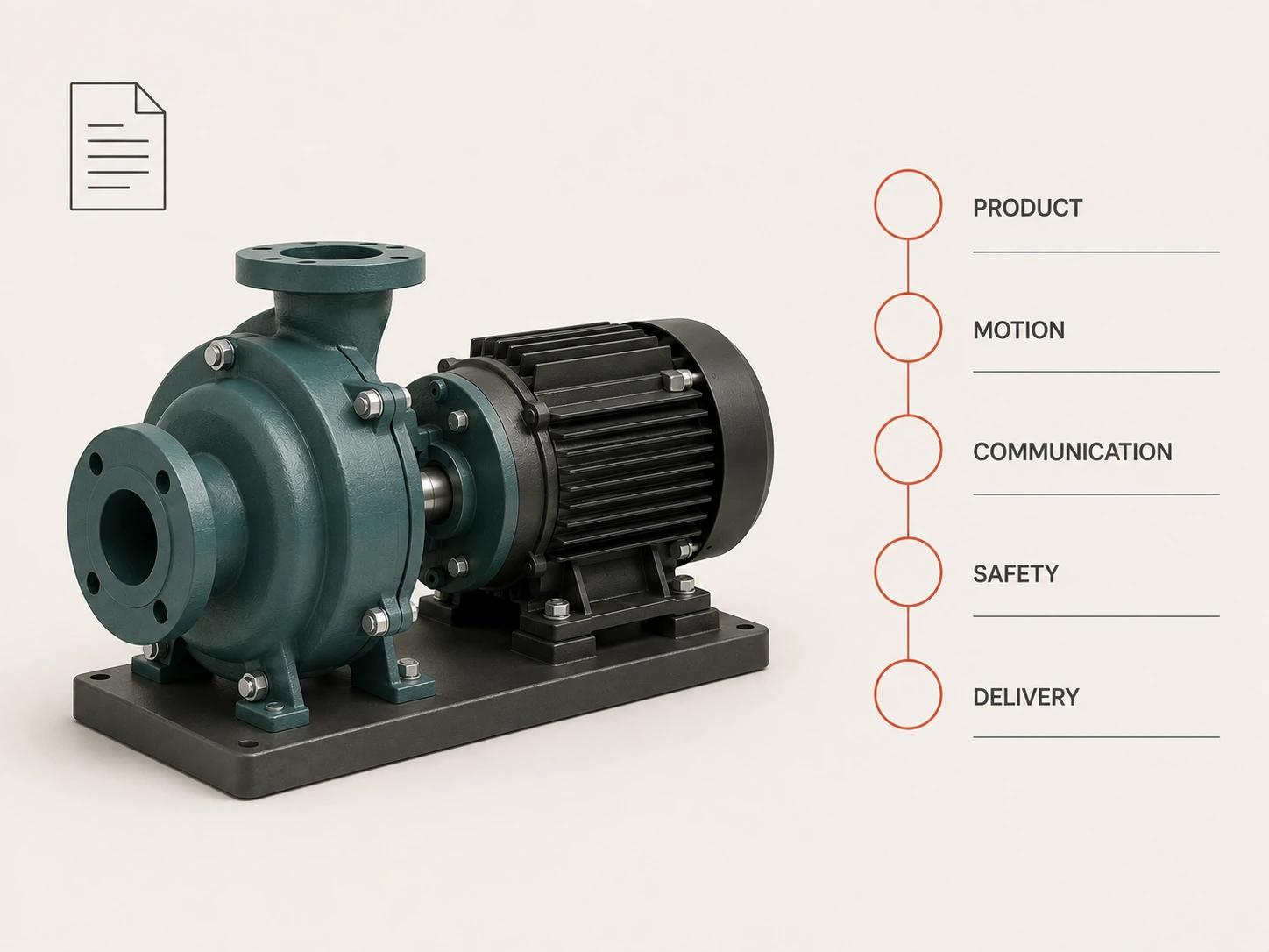
The following review table is another Double Edged editorial framework. A project may add legal, regulatory, localization or accessibility review based on its destination.
| Review gate | Reviewer asks | Evidence to inspect | Reject when |
|---|---|---|---|
| Product truth | Is this the approved configuration and component relationship? | Model revision, product hierarchy, materials, interfaces and cut-plane review | Geometry is reconstructed without declared assumptions or the wrong variant is shown |
| Motion truth | Does each displacement or state change say only what we can support? | Storyboard states, axes, clearances, timing and source procedure where applicable | Parts intersect, order is implied without authority, or reversal suggests an unapproved task |
| Communication | Can the intended audience identify the subject and takeaway at delivery size? | Camera, holds, ghosting, labels, crops, narration and compression test | The focal mechanism is hidden, labels drift, or visual devices compete |
| Safety boundary | Is the purpose clear, and are safety-relevant elements controlled by the right owner? | Use statement, approved instructions, risk records, warnings, jurisdiction and sign-off | The animation substitutes generic steps for an applicable instruction or procedure |
| Delivery integrity | Did the approved content survive the final export? | Final file, frame rate, resolution, captions, locale, version ID and destination playback | The review file differs from delivery or a post-approval edit lacks a new identity |
Review the rendered export, not only the 3D scene. Motion blur can hide a fastener, compression can soften a small label, and a platform crop can remove a limitation. Those are communication failures even when the underlying model is correct.
Build the brief around evidence and handoffs
A useful brief brings together the approved model or source evidence, configuration list, audience, use statement, key questions, governing documents, terminology, destination specifications and named reviewers. Keep uncertainty visible instead of burying it inside the model.
Production can then move from source audit and visual strategy through storyboard states, model and motion review, look development, labelled previews, any required safety review, final rendering and export verification. The broader client approvals and handoffs are covered in 3D Animation Video Production: A Client’s Stage-by-Stage Guide.
Use the compact-pump sequence plan and the review-gate table together. First confirm that every shot has one question, a suitable visual device and supporting evidence. Then assess product truth, motion truth, communication, safety boundary and delivery integrity. For direct service scope, the 3D product animation service is the commercial destination; this article remains a technical planning guide.
Bring the real product question to the review
Share the product configuration, approved source material, intended audience and the one internal relationship or sequence that viewers must understand. That is enough to identify whether an exploded view, cutaway, ghosted state or controlled sequence belongs in the scope without inventing authority the source material does not provide.